Development of Digital Smart Voltage Meter Based on Digital Integrated Circuits
In order to solve the intelligent problems of automatic digital voltmeter automatic conversion range, measured voltage polarity judgment, amplitude conversion, over-range display, and alarm signal, digital circuit chips are used to achieve the intelligent use of voltage meter functions through digital logic control relationships. The circuit design principle is clarified, and the composition of the circuit system, the functions and characteristics of each circuit, the selection of circuit components, and the signal processing process are described. Through physical verification, the design function was realized, and a self-made digital smart voltmeter was designed.
0 Preface
The general digital electricity measurement meter widely used in the market today does not solve the problem of automatic range conversion. When the measurement operation is still performed, the measurement range is still switched by manually pulling the switch. It is a difficult point to measure the intelligent design of the meter. In the existing smart meters, most of the intelligent functions are implemented using a single-chip microcomputer control circuit or a bidirectional shift register. The disadvantages are that the circuit system and the range control signal are complicated to produce, and debugging and production are difficult and the reliability is poor. In fact, the circuit system can be completely composed of commonly used digital integrated circuits, and functions such as automatic conversion between multiple ranges can be realized by combining logic functions.
1 The box structure of the circuit system
The circuit system consists of a tested input voltage polarity detection and conversion circuit, a voltage amplitude conversion circuit, a range automatic control conversion signal generation circuit, a multiplex analog switch switching circuit, a range control amplification circuit, an A/D conversion circuit, and a display circuit. As shown in Figure 1.
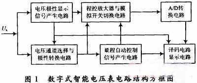 The function of each part of the circuit in Figure 1 is:
(1) Voltage polarity display signal generation circuit: The voltage comparator generates a "+" or "-" polarity display signal according to the polarity of the measured voltage.
(2) Voltage channel selection and polarity conversion circuit: There are two channels, for the positive polarity voltage is passed by channel 1, if the negative polarity voltage is passed by channel 2, then converted to positive polarity and output.
(3) Range automatic control signal generation circuit: determine the measurement range (range) of each segment according to the measured voltage level, generate range automatic conversion control signal, overrange display and alarm signal, and control the position of the decimal point of each range.
(4) Program-controlled amplifier and analog switch switching circuit: Select different channels under the function of automatic range conversion control signal, and amplify or attenuate a certain range of input voltage and send it to A/D converter.
(5) A/D conversion circuit: converts an analog voltage signal into a digital signal.
(6) Decoding and Display Circuit: After the digital signal is decoded, the digital tube displays the measurement result.
2 circuit schematics
The digital smart voltmeter circuit principle constructed according to Figure 1 is shown in Figure 2. The main components of the figure are as follows:
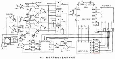 U1 (LM324) is a quad op-amp IC1, and U1-1/4 and U1-2/4 function to generate a signal voltage polarity identification signal and control U2 signal path. U1-3/4 constitutes a program-controlled amplifier circuit that performs amplification, or attenuation, of 10, 1, 1/10, and 1/100 of the voltage under test. U1-4/4 is an inverting amplifier used to adjust the output voltage amplitude to meet the normal operating requirements of the A/D converter;
U2 (SGM522) is a two-channel analog switch IC, which realizes the positive and negative polarity measured voltage sub-channel transmission, so that the negative polarity signal can be inversely processed;
U3 (C4066) is a four-channel analog switch IC. Under the influence of the automatic range control signal, the voltage of different ranges can be divided and transmitted in order to match the amplitude of U1-3/4 voltage.
U4 (LM339), U5 (74LS05), U6 and U7 (74LS21) constitute the automatic range control signal generation circuit. Among them, U4 is a quadrature comparator IC, which is used to determine the measuring range of each range. U5 is a quad inverter, which implements inverse transformation of high or low level. U6 and U7 are four-input dual AND gate ICs. The operation gets automatic range control signal;
U8 (C14433) is a double-integrating A/D converter (also known as a dual-slope A/D converter). The conversion output is proportional to the average value of the input signal, and it is good for AC interference superimposed on the input signal. Inhibitory effect, 3-1/2-digit (BCD code) monolithic dual-integration A/D conversion function with zero-drift compensation, conversion rate of 3 to 10 Hz, conversion accuracy of ±1LSB, analog input voltage range of 0 to ±1.999 V or 0 ~ ± 199.9mV, input impedance greater than 100MΩ. The conversion result of MC14433 is in the form of BCD code, which is output from Q0 to Q3 according to one, one hundred, ten, and one bit respectively. The corresponding bit strobe signal is provided by DS1~DS4.
U9 (MC14511B) is a decoding integrated circuit, which decodes the BCD code into a decimal signal and controls the bit display of the digital tube.
U10 (MC1413) is a 7-way inverting buffer integrated circuit used to achieve the conversion between high and low levels, and enhance the drive capability of digital display tubes.
3 circuit works
(1) The Ux polarity of the voltage under test is determined and the operating principle of the conversion circuit: The circuit consists of two zero-crossing voltage comparators, an inverter, and a bidirectional limiter circuit. When Ux polarity is “+â€, U1- The 1/4 output is high and the measured voltage passes through the U2's first channel under the control of C+. U1-2/4 output low, C is also low, U2's second channel is unblocked; when Ux polarity is "-". U1-2/4 outputs a high level, and under the control of C, the measured voltage passes through the second channel of U2, and the inverse transformation is performed through U5-1-4. U1-1/4 outputs a low level and C+ disables the first channel of U2. V1, V2 are bidirectional limiting diodes that limit the voltage amplitude applied to the U1-1/4 and U1-2/4 inputs.
(2) Multi-channel analog switch and program-controlled amplifier circuit working principle: The circuit consists of C4066, U1-3/4, R4 ~ R7 and other components. Let R1 ~ R3 channel equivalent resistance is R1 ~ 3, its size can be set to 100kΩ, when B1 is high, multiple analog switch C4066 i1 ~ O1 channel is connected, op amp U1-3/4 feedback resistance R4 takes 1MΩ, and Ux is amplified 10 times and sent to the input of the A/D converter. If the voltage full scale value of A/D conversion is 2V, the voltage of 0-±200mV can be measured. Similarly, when the range conversion control signals B2, B3, and B4 are respectively high, the corresponding channel of the C4066 is turned on. When the feedback resistances R5, R6, and R7 of the U1-3/4 are 100kΩ, 10kΩ, and 1kΩ, respectively, R5. The voltage of ±200 mV to ±2 V is directly passed, and R6 attenuates the voltage of ±2 to ±20 V by 10 times and passes it. R7 attenuates the voltage of ±20 to ±200 V by 100 times and then passes it. Then the output voltage of one circuit is inverted and amplified by U1-4/4 so that it is consistent with the polarity of the actual voltage, and the voltage amplification factor (-R16/R15) can be adjusted by R16 to ensure the normal operation of the A/D conversion circuit. The input voltage.
(3)Automatic range conversion control circuit working principle: The range automatic conversion circuit consists of four 4 comparators U4, three inverters (in U5), two four-input dual AND gates U6 and U7, voltage divider resistors R10 to R14, etc. composition. Since R1~3 are set to 100kΩ, R8 (470kΩ adjustable) and R9 (5kΩ) are selected so that the voltage division ratio of ux on R9 is 1/100, which is applied to the inverting input terminal of each comparator after being divided. When ux is ±200mV, ±2V, ±20V, ±200V, respectively, the voltage values ​​are 2mV, 20mV, 0.2V, 2V. At the same time, the reference levels of the comparators obtained from R10 to R14 (resistance values ​​shown in Figure 2) for Vcc voltage division are also 2mV, 20mV, 0.2V, and 2V, respectively, and are added to the non-inverting input of each comparator. end. When the voltage Ux reaches the full-scale value of a certain range, the output level of the comparator is changed from high to low, and the range automatic control and flag signals (active high level) are generated by the combination logic circuit. If Ux is in the range of 0 to ±200mV, U6-1/2 outputs a high level to obtain an effective range control signal B1, and the remaining B2 to B3 are low levels. Similarly, when the measured voltage is ±2V, ±2 to ± 20V, ±20 ~ ± 200V range, U6-2/2, U7-1/2, U7-2/2 respectively output high, get range control signals B2, B3 and B4, state conversion table as shown in Table 1. Show.
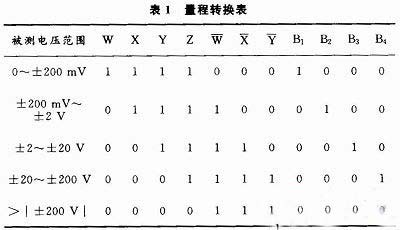
The logical expressions are: B1=W·X·Y·Z, which is the over-range flag signal.
(4) Indication voltage polarity, decimal point position and over-range indication signal: The polarity of the voltage to be measured display control signal is provided by U1-2/4, and the output high or low level controls "-" or "+" No. display; decimal point position control signal is realized by automatic conversion control signal of range, high level of B1 is used to display the decimal point position with measurement range of 0~±200mV, high level of B2 is used to display measurement range of ±200mV~± The decimal point of 2V, the high level of B3 is used to display the decimal point position of the measurement range of ±2 to ±20V, and the high level of B4 is used to display the decimal point position of the measuring range of ±20 to ±200V when the voltage range to be measured. Outside ±200V, no decimal point is used; the overrange indication signal is implemented by the low level of B4, and when B4 is low, the measured voltage exceeds the upper limit of ±200V.
(5)A/D conversion, decoding, display circuit working principle: Use the signal output by U1-2/4 to control the bright and unlit of the “g†segment of the highest digit of the digital tube, and realize the polarity “-†display. When U4's 4 comparators output a high level, an over-range condition occurs, which can be used to generate alarms and over-display signals (not considered by the system). When the signal output from the programmable amplifier is applied to pin 3 of U8, the analog voltage is converted into a BCD code and output from pins 20, 21, 22, and 23, and is decoded into thousands, hundred, ten, and four decimal digits by U9. At the same time, the corresponding strobe signals are output from the 16th, 17th, 18th, and 19th pins of U8 to jointly control the digital tube display measurement results.
4 Conclusion
The measurement system uses a combination of AND gates, inverters, comparators, and multiple analog switch integrated circuits (C4066) to obtain voltage polarity judgment, automatic range conversion, signal amplitude conversion, and decimal point position display control. Over-range display and alarm signal. The circuit structure design may seem complicated, but there are few discrete components and the cost is low. With the advantages of convenient setting range, wide voltage measurement range, relatively independent functions, easy expansion, and stable and reliable operation, it is worth learning from.
0 Preface
The general digital electricity measurement meter widely used in the market today does not solve the problem of automatic range conversion. When the measurement operation is still performed, the measurement range is still switched by manually pulling the switch. It is a difficult point to measure the intelligent design of the meter. In the existing smart meters, most of the intelligent functions are implemented using a single-chip microcomputer control circuit or a bidirectional shift register. The disadvantages are that the circuit system and the range control signal are complicated to produce, and debugging and production are difficult and the reliability is poor. In fact, the circuit system can be completely composed of commonly used digital integrated circuits, and functions such as automatic conversion between multiple ranges can be realized by combining logic functions.
1 The box structure of the circuit system
The circuit system consists of a tested input voltage polarity detection and conversion circuit, a voltage amplitude conversion circuit, a range automatic control conversion signal generation circuit, a multiplex analog switch switching circuit, a range control amplification circuit, an A/D conversion circuit, and a display circuit. As shown in Figure 1.
(1) Voltage polarity display signal generation circuit: The voltage comparator generates a "+" or "-" polarity display signal according to the polarity of the measured voltage.
(2) Voltage channel selection and polarity conversion circuit: There are two channels, for the positive polarity voltage is passed by channel 1, if the negative polarity voltage is passed by channel 2, then converted to positive polarity and output.
(3) Range automatic control signal generation circuit: determine the measurement range (range) of each segment according to the measured voltage level, generate range automatic conversion control signal, overrange display and alarm signal, and control the position of the decimal point of each range.
(4) Program-controlled amplifier and analog switch switching circuit: Select different channels under the function of automatic range conversion control signal, and amplify or attenuate a certain range of input voltage and send it to A/D converter.
(5) A/D conversion circuit: converts an analog voltage signal into a digital signal.
(6) Decoding and Display Circuit: After the digital signal is decoded, the digital tube displays the measurement result.
2 circuit schematics
The digital smart voltmeter circuit principle constructed according to Figure 1 is shown in Figure 2. The main components of the figure are as follows:
U2 (SGM522) is a two-channel analog switch IC, which realizes the positive and negative polarity measured voltage sub-channel transmission, so that the negative polarity signal can be inversely processed;
U3 (C4066) is a four-channel analog switch IC. Under the influence of the automatic range control signal, the voltage of different ranges can be divided and transmitted in order to match the amplitude of U1-3/4 voltage.
U4 (LM339), U5 (74LS05), U6 and U7 (74LS21) constitute the automatic range control signal generation circuit. Among them, U4 is a quadrature comparator IC, which is used to determine the measuring range of each range. U5 is a quad inverter, which implements inverse transformation of high or low level. U6 and U7 are four-input dual AND gate ICs. The operation gets automatic range control signal;
U8 (C14433) is a double-integrating A/D converter (also known as a dual-slope A/D converter). The conversion output is proportional to the average value of the input signal, and it is good for AC interference superimposed on the input signal. Inhibitory effect, 3-1/2-digit (BCD code) monolithic dual-integration A/D conversion function with zero-drift compensation, conversion rate of 3 to 10 Hz, conversion accuracy of ±1LSB, analog input voltage range of 0 to ±1.999 V or 0 ~ ± 199.9mV, input impedance greater than 100MΩ. The conversion result of MC14433 is in the form of BCD code, which is output from Q0 to Q3 according to one, one hundred, ten, and one bit respectively. The corresponding bit strobe signal is provided by DS1~DS4.
U9 (MC14511B) is a decoding integrated circuit, which decodes the BCD code into a decimal signal and controls the bit display of the digital tube.
U10 (MC1413) is a 7-way inverting buffer integrated circuit used to achieve the conversion between high and low levels, and enhance the drive capability of digital display tubes.
3 circuit works
(1) The Ux polarity of the voltage under test is determined and the operating principle of the conversion circuit: The circuit consists of two zero-crossing voltage comparators, an inverter, and a bidirectional limiter circuit. When Ux polarity is “+â€, U1- The 1/4 output is high and the measured voltage passes through the U2's first channel under the control of C+. U1-2/4 output low, C is also low, U2's second channel is unblocked; when Ux polarity is "-". U1-2/4 outputs a high level, and under the control of C, the measured voltage passes through the second channel of U2, and the inverse transformation is performed through U5-1-4. U1-1/4 outputs a low level and C+ disables the first channel of U2. V1, V2 are bidirectional limiting diodes that limit the voltage amplitude applied to the U1-1/4 and U1-2/4 inputs.
(2) Multi-channel analog switch and program-controlled amplifier circuit working principle: The circuit consists of C4066, U1-3/4, R4 ~ R7 and other components. Let R1 ~ R3 channel equivalent resistance is R1 ~ 3, its size can be set to 100kΩ, when B1 is high, multiple analog switch C4066 i1 ~ O1 channel is connected, op amp U1-3/4 feedback resistance R4 takes 1MΩ, and Ux is amplified 10 times and sent to the input of the A/D converter. If the voltage full scale value of A/D conversion is 2V, the voltage of 0-±200mV can be measured. Similarly, when the range conversion control signals B2, B3, and B4 are respectively high, the corresponding channel of the C4066 is turned on. When the feedback resistances R5, R6, and R7 of the U1-3/4 are 100kΩ, 10kΩ, and 1kΩ, respectively, R5. The voltage of ±200 mV to ±2 V is directly passed, and R6 attenuates the voltage of ±2 to ±20 V by 10 times and passes it. R7 attenuates the voltage of ±20 to ±200 V by 100 times and then passes it. Then the output voltage of one circuit is inverted and amplified by U1-4/4 so that it is consistent with the polarity of the actual voltage, and the voltage amplification factor (-R16/R15) can be adjusted by R16 to ensure the normal operation of the A/D conversion circuit. The input voltage.
(3)Automatic range conversion control circuit working principle: The range automatic conversion circuit consists of four 4 comparators U4, three inverters (in U5), two four-input dual AND gates U6 and U7, voltage divider resistors R10 to R14, etc. composition. Since R1~3 are set to 100kΩ, R8 (470kΩ adjustable) and R9 (5kΩ) are selected so that the voltage division ratio of ux on R9 is 1/100, which is applied to the inverting input terminal of each comparator after being divided. When ux is ±200mV, ±2V, ±20V, ±200V, respectively, the voltage values ​​are 2mV, 20mV, 0.2V, 2V. At the same time, the reference levels of the comparators obtained from R10 to R14 (resistance values ​​shown in Figure 2) for Vcc voltage division are also 2mV, 20mV, 0.2V, and 2V, respectively, and are added to the non-inverting input of each comparator. end. When the voltage Ux reaches the full-scale value of a certain range, the output level of the comparator is changed from high to low, and the range automatic control and flag signals (active high level) are generated by the combination logic circuit. If Ux is in the range of 0 to ±200mV, U6-1/2 outputs a high level to obtain an effective range control signal B1, and the remaining B2 to B3 are low levels. Similarly, when the measured voltage is ±2V, ±2 to ± 20V, ±20 ~ ± 200V range, U6-2/2, U7-1/2, U7-2/2 respectively output high, get range control signals B2, B3 and B4, state conversion table as shown in Table 1. Show.
The logical expressions are: B1=W·X·Y·Z, which is the over-range flag signal.
(4) Indication voltage polarity, decimal point position and over-range indication signal: The polarity of the voltage to be measured display control signal is provided by U1-2/4, and the output high or low level controls "-" or "+" No. display; decimal point position control signal is realized by automatic conversion control signal of range, high level of B1 is used to display the decimal point position with measurement range of 0~±200mV, high level of B2 is used to display measurement range of ±200mV~± The decimal point of 2V, the high level of B3 is used to display the decimal point position of the measurement range of ±2 to ±20V, and the high level of B4 is used to display the decimal point position of the measuring range of ±20 to ±200V when the voltage range to be measured. Outside ±200V, no decimal point is used; the overrange indication signal is implemented by the low level of B4, and when B4 is low, the measured voltage exceeds the upper limit of ±200V.
(5)A/D conversion, decoding, display circuit working principle: Use the signal output by U1-2/4 to control the bright and unlit of the “g†segment of the highest digit of the digital tube, and realize the polarity “-†display. When U4's 4 comparators output a high level, an over-range condition occurs, which can be used to generate alarms and over-display signals (not considered by the system). When the signal output from the programmable amplifier is applied to pin 3 of U8, the analog voltage is converted into a BCD code and output from pins 20, 21, 22, and 23, and is decoded into thousands, hundred, ten, and four decimal digits by U9. At the same time, the corresponding strobe signals are output from the 16th, 17th, 18th, and 19th pins of U8 to jointly control the digital tube display measurement results.
4 Conclusion
The measurement system uses a combination of AND gates, inverters, comparators, and multiple analog switch integrated circuits (C4066) to obtain voltage polarity judgment, automatic range conversion, signal amplitude conversion, and decimal point position display control. Over-range display and alarm signal. The circuit structure design may seem complicated, but there are few discrete components and the cost is low. With the advantages of convenient setting range, wide voltage measurement range, relatively independent functions, easy expansion, and stable and reliable operation, it is worth learning from.
90 Degree Elbow,Stove 90 Degree Elbow,90 Degree Elbow Pipe,90 Degree Elbow Pvc
Jinan Huancheng Heating Equipment Manufacturing Co., Ltd. , https://www.globalstove.com