Rod air compressor noise analysis and tanning
Compressor noise test and result analysis Compressor noise test According to GB/T4980, four measuring points are selected around the screw compressor to measure the noise. The screw compressor measuring point distribution is as shown. The screw compressor measuring point noise test sensor adopts Danish B/K microphone 4189 and preamplifier 2671. The data acquisition system adopts NI Xi's PXI4472B acquisition card and PXI hardware platform. The software is based on Labview designed compressor vibration noise. analysis system.
The test parameters are selected as follows: sampling frequency 51.2 kHz, sampling length 8192, sound level using A weighting evaluation, spectrum analysis using 1/3 octave analysis, analysis frequency range is 20 Hz 20 kHz. The test system is as shown.
The test system diagram is designed to test the compressor noise in five test cases: the noise level of the noise floor of each measuring point and the noise spectrum; the A-weighted sound pressure level of each measuring point under normal working conditions of the unit And noise spectrum; A-weighted sound pressure level and noise spectrum of each measuring point when the unit is opened under normal working conditions; A-weighted sound pressure level and noise of each measuring point when the box cover is opened only in the motor state Spectrum; % unit does not inhale during working conditions, A-weighted sound pressure level and noise spectrum of each measuring point when the box cover is opened. The measured sound pressure level data of each measuring point A is as shown. The 1/3 octave data of each measurement point noise is as shown.
Each working condition A counts the sound pressure level horizontal measuring point 1/3 octave data. Analysis of test results (1) It can be seen that the noise sound pressure level is already high in the state where only the motor is started, and the data of each measurement point reflects this point, and the motor noise should be the main noise source of the compressor.
From the comparison of the switch gate status test data: the measurement point 1 is 8dB (A); the measurement point 2 is 13dB (A); the measurement point 3 is 12dB (A); the measurement point 4 is 1dB (A), the analysis is due to the motor The opening of the tuyere is caused by a serious weak link on the side of the measuring point 4. From the state test data of the air intake not inhaling, the influence of the suction noise is low, which is not the main noise source of this type of compressor. (2) It can be seen from the 1/3 octave data of the middle, when the compressor is in normal operation (closed state), the sound pressure level of measuring point 1 and measuring point 3 is higher at the center frequency of 31.5 Hz--2000 Hz. Point 2 has a higher sound pressure level at the center frequency of 50 Hz - 2000 Hz, and the sound pressure level of point 4 at the center frequency of 31.5 Hz - 5000 Hz is higher. The sound insulation cover (opening state) and the air inlet are not inhaled. The sound pressure levels of the four measuring points at the center frequency of 50 Hz to 5000 Hz are higher. In the single-turn motor state, the sound pressure level is higher at the center frequency of 50 Hz to 5000 Hz. Therefore, the main frequency component of compressor noise is in the range of 502 kHz, especially 50500 Hz. Combined with the theoretical analysis of the noise source, the center frequency is 49.5 Hz and 100 Hz and the corresponding multiplier sound pressure level is the main source of motor noise; the center frequency is The sound pressure level of 50Hz-2000Hz is mainly derived from the driving gear noise and bearing noise of the compressor. (3) The overall noise of each measuring point is higher than the 80dB (A) specified by the national standard.
Based on the above analysis, the main reasons for the noise exceeding the standard are: unreasonable structure of the air inlet of the motor, main noise source of the motor, noise source of the driving gear, noise source caused by bearing vibration, and noise source of suction and exhaust.
Noise control scheme determination and noise reduction effect 3.1 Determination of noise control scheme From the test results analysis, the noise control scheme is carried out from the following two aspects: the structure of the motor air inlet is improved; on the basis of still using the sound insulation cover, the sound absorbing material is Feature correction.
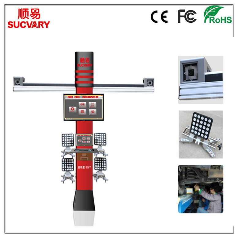
3D Wheel Alignment With Stand Column has no cabinet. It has a stand colum which can hold LCD screen and wheel clamps for targets. These 3D Wheel Alignment are for shops with limited space. Compared with a cabinet, the stand column only takes up small space. We have updated the design of stand column which makes the wheel alignment looks great! Its texture is aluminum alloy which is very solid and strong.
Advantages of Sucvary 3D Wheel Alignment:
1. Cloud 3D wheel alignment can save space with different installation patterns.
2. Cloud 3D wheel alignment has 3 cameras, the reference plane is car body, so Cloud 3D wheel alignment can measure almost all kinds of vehicles.
3. Cloud 3D wheel alignment supports varied operation platforms, point to point transmission by WiFi can shied interference.
4. Supported by powerful cloud service, Cloud 3D wheel alignment can connect to IPAD, cell phone, computer and the Internet, supporting remote shunting operation and data upgrade.
5. Four targets are crash resistant and can be exchanged. Fix wheel claws without taking apart wheel hub cover.
6. Measurement range is wide, and Cloud 3D wheel alignment can also test wheel deviationbesides all traditional parameters.
7. The optional one point wheel clamps can be installed within four seconds.

3D Wheel Alignment With Stand Column
3D Wheel Alignment With Stand Column
Shenzhen Sucvary Tech Co., Ltd. , http://www.syalignment.com