Finite Element Analysis and System Design of Forklift Gantry
Finite Element Analysis and System Design of Forklift Gantry

Baoji Heli Forklift Factory Wu Jinggang Zhang Zhancang
Chang'an University Ma Pengfei
[ Abstract] : This paper uses the finite element method to calculate the simplified gantry, and designs the finite element calculation and analysis software to provide a feasible method and means for the gantry design, and also for the calculation of other engineering machinery structures. for reference.
[ Keywords] : The finite element analysis method of forklift gantry finite element software is widely used in engineering field, and is an important method and means for scientific research and engineering analysis. For the forklift frame, the design usually only pays attention to the calculation of the main force points, and lacks effective means for the calculation of the whole structure. The finite element calculation method is used to analyze the forklift frame to provide users with an intuitive and convenient operating environment. Master the force status of the forklift frame to provide a basis for design.
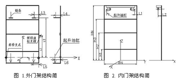
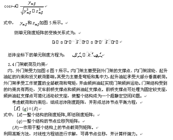
1. Calculation model of forklift frame structure <br> The connection between the inner and outer gantry of the forklift is realized by the roller stuck in the channel steel. The number of beams is variable, determined by the maximum lifting height of the forklift, and the maximum number of inner gantry beams. 4, the minimum is 2; the outer girders are up to 5 and at least 4. When the gantry is lifted, the lifting hoist lifts the inner gantry and drives the fork to achieve the purpose of lifting the load. The swinging of the outer gantry is achieved by tilting the cylinder, and the swinging shaft is the front axle, and the entire working device swings in the range of 12 degrees.
For the convenience of calculation and analysis, the structure of the gantry is simplified. The structure and parameters of the inner and outer gantry are shown in Figures 1 and 2. Considering the structure of the gantry, the movement and the form of the force, the inner and outer gantry are subjected to finite element calculation and analysis according to the space beam.
2.1 Unit Node Displacement and Node Force <br> For the space beam element, its node displacement and nodal force are shown in Figure 3.
Unit's i-node displacement column matrix:

J-node displacement column matrix

Unit node displacement column matrix

Unit i-node force matrix

J-node force matrix:

Unit node force matrix:

2.2 Element stiffness matrix element stiffness equation

among them
 For the element stiffness matrix,
  For the rod end displacement.
 The element stiffness matrix in the above stiffness equation can be divided into four sub-matrices, then
 It can be seen from this that the space beam element has 12 degrees of freedom and its stiffness matrix is ​​a 12×12 order matrix (omitted).
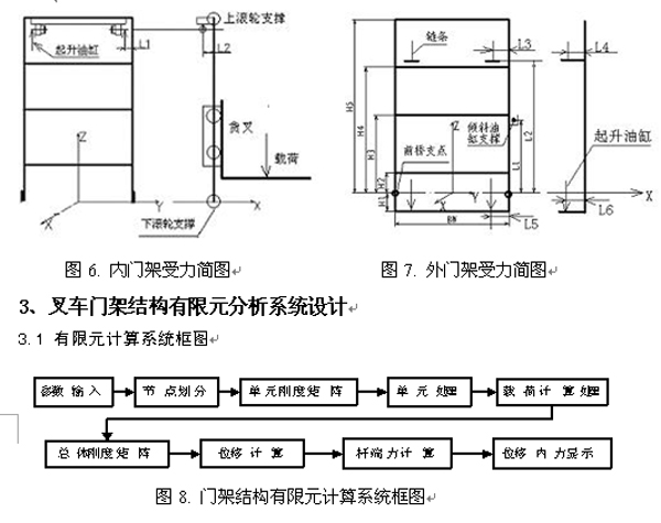
The structure is divided into nodes according to the beam unit, load processing, unit stiffness matrix calculation, overall stiffness matrix calculation, displacement calculation, rod end force calculation. The structural calculation program uses vb programming to directly view the calculation results, such as displacement, stress, and internal force.
4. Finite element calculation software system design <br>The system design mainly includes three parts: parameter input, node division, finite element calculation and result display.
The parameter input includes load parameters, structural parameters and material parameters. The column is made of channel steel, the beam is made of A3 steel, and its cross section is rectangular. Therefore, in the system design, the material database is used to store the relevant parameters of the channel steel. The user only needs to select the channel steel model in use, and the height and width of the section are required for the beam.
The main work of the node partitioning and finite element calculation part is all in the background, and the window design is relatively simple, but the program it calls is the core of the system.
The results show that there are two ways to express the curve display and the data display. The curve shows the drawing of the internal force diagram using the Picturebox control, using the data file and the drawing module, as shown in Figure 12 for the outer door frame bending moment diagram. The data display is implemented by calling the corresponding "*.txt" file generated by the finite element calculation through the Richtextbox control of vb.
5 , the conclusion <br> Through the analysis of the forklift frame, establish its calculation model, and describe and deduct the coordinate transformation problem under the space coordinates, on this basis to develop and design the forklift gantry finite element calculation and analysis software system, Provide effective means and methods for the calculation of forklift gantry.
[references]:
[1] Liu Jiqing, "Structural Mechanics", National Defense Industry Press, April 1985, Beijing [2] Lei Xiaoyan, "Finite Element Method", China Railway Publishing House, October 2000 [3] Liu Erlie, "Finite Element Method and Programming", Tianjin University Press, July 1999 [4] Qingyuan Computer Studio compiled "Visual Basic 6.0" development Baodian Machinery Industry Press, April 1999
Finger Protector,Thumb Protector,Silicone Finger Protectors,Silicone Finger Cover
Shandong Changyun Musical Instruments Co., Ltd. , https://www.cyukulele.com