How to create a bending fatigue test for your metal materials
This standard specifies the technical requirements, inspection methods, inspection rules and signs, packaging, transportation and storage of the pure bending fatigue tester.
This standard applies to metal test, sample rotation of the pure bending fatigue face machine (hereinafter referred to as testing machine). It is also applicable to the test machine used in special conditions (such as high temperature, corrosive media, ambient atmosphere, etc.), but this standard does not specify these special conditions.
Working conditions:
1, the ambient temperature: 10 °C a 35 °C
2, the relative humidity of air does not exceed 85%
3, the environment is free of vibration and away from the noise source 4, on the basis of a solid installation 5, the power supply voltage fluctuation does not exceed ± 10% of the rated value
skills requirement:
1, the maximum speed of the rotating speed tester is generally 10000r/min
2. The initial bending moment of the initial bending moment tester should be as small as possible, and the initial bending moment should not be greater than 10% of the maximum bending moment of the testing machine.
3. The relative error of the bending moment and the repeatable error tester starts from 10% of the maximum bending moment and reaches the maximum bending moment of the tester. The maximum allowable value of the bending moment relative error is ±1% of the nominal value of the bending moment;
The test machine starts from 10% of the maximum bending moment and reaches the maximum bending moment of the testing machine. The maximum allowable value of the bending moment repeatability error is 1% of the nominal value of the bending moment.
4. The relative bending moments of the left and right moments should be equal to the bending moments applied to the left and right sides of the specimen. The relative difference should not exceed 1% of the nominal value of the unilateral bending moment.
5. The radial run-out of the test bars sandwiched between the left and right spindles in the middle of the left and right chucks should not exceed 0.02 mm.
6. The height difference between the left and right chucks should not exceed 0.1mm when the left and right chuck heights clamp the specimen.
Article from: Jinan Zhongchuang Industrial Testing System Co., Ltd. Technical Department
Characteristics:
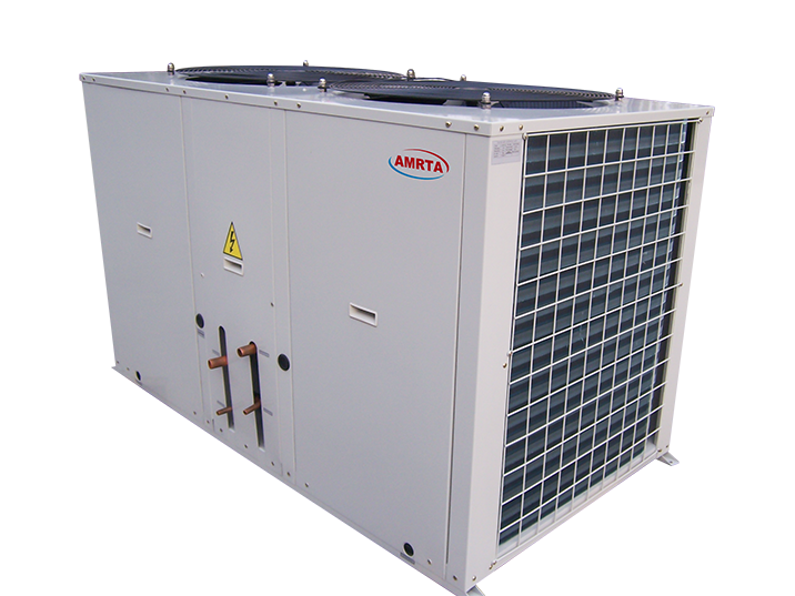
11 sizes available ranging from 19.5kW to 103.7kW cooling capacity.
Panels and frame are made from metal steel protected with polyseter powder painting to ensure total resistance to atmospheric agents.
High efficiency scoll compressor for the whole range, with built-in thermal overload cut-out and crankcase heater, mounted on rubber vibration dampers.
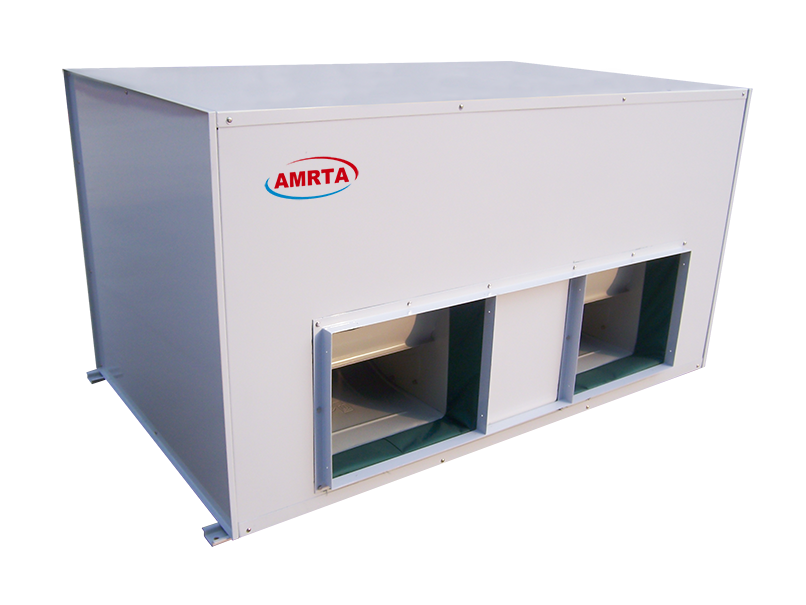
Indoor Ducted Split Unit with long air supply distance. Pre G4, Medium F7/F8 and HEPA H13 can be within the indoor Air Conditioner if needed.
Split installation, connected by means of flare/welding coupling.


Ducted Split Unit
Ducted Split Unit,Air Conditioner Ducted Split Unit,Duct Split Fan Coil Unit,High Quality Ducted Split Unit
Jinan Amrta Air Conditioning Co.,Ltd , https://www.amrtaac.com