Improvement of Grinding Method for High Precision Steel Roller and Hollow Slender Shaft
First, large-scale high-precision roller surface grinding method
The figure shows a large, high position precision roll made of 45 steel. Originally, when grinding on the M1450 universal grinding machine, use the center hole at both ends of the workpiece to locate, roughen the roller surface, fine grinding the bearing positions at both ends, and then use the bearing position to locate, use a dial gauge to check, the radial runout error of the roller surface. 10 times more than the pattern requirements (0.04 ~ 0.06mm). Trying to improve the number of trials has not been improved, far less than the radial requirements of the pattern of 0.003mm. Therefore, on the basis of continuous summing up of experience, the following new method was used to grind a few roots and reached the requirements of the pattern.
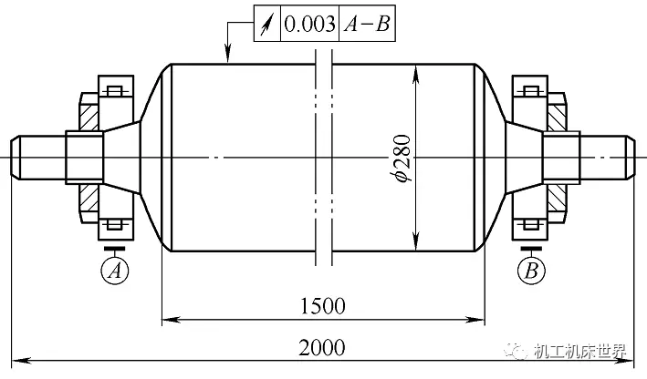
In the machining process, when selecting a positioning reference, the principles of reference coincidence, reference integration, and mutual reference should be followed to achieve high positional accuracy. When this roller is tested and assembled, it uses the bearing position as a reference. Therefore, in the grinding process, the bearing position should also be used as a positioning reference to achieve the principle of benchmarking, unity and mutual benchmarking.
In front of the grinding roller, first use the center hole at both ends of the workpiece to position the roller neck (two bearing positions) to the required level. Then check the bearing mounted on both ends of the bearing position, and use a nut to adjust the gap between the two bearings, to meet the requirements of the assembly.
When grinding the roller surface, first use the center hole at the two ends of the workpiece and the two tips of the grinding machine to position, and then use two closed center frames to stand on the outer circle of the bearing at both ends. After racking the center frame, the top ends of the two ends are withdrawn from the center hole of the workpiece. The centerpiece chuck is installed at the left end of the workpiece, and the grinding head frame is used to drive the workpiece to rotate to perform semi-finishing. During the final grinding, the grinding wheel must be properly dressed to keep the grinding wheel sharp and reduce the grinding depth to reduce the grinding force. It is also necessary to lower the hydraulic pressure of the grinding machine guide rails to reduce the thickness of the guide rail oil film to increase the rigidity of the guide rails, but the table must be made to move without crawling. After grinding to the process diameter, two or three strokes must be performed without sparking. After grinding in this way, on the large platform, the journal is supported on the bearing with two equal height V-shaped irons, and the dial of the dial is used to detect that the radial runout of each part of the roller surface is less than 0.003mm.
Second, the hollow elongated shaft grinding method
Workpieces with a wall thickness of about 1/6 of the hole diameter and an aspect ratio of more than 15 are called hollow elongated shafts. The blanks of this type of workpiece are mostly thick-walled seamless steel tubes or piston rods and test bars that have been drilled through the drilled holes. Their wall thickness is not uniform, and they increase the internal stress after turning the outer circle. When coupled with the hole block grinding outer circle, the heat generated can easily lead to deformation of the workpiece and non-uniform heat conduction, often produce single-sided grinding phenomenon (abrasive grinding spark intermittently, sometimes sometimes), directly affect the roundness of the workpiece after grinding, Therefore, it becomes a big problem in grinding.
Grinding the outer circle is necessary before grinding such workpieces. In order to facilitate the clamping, the two ends of the workpiece are first flattened and rounded in the inner hole, and then holes with C-shaped central holes are installed in the inner holes at both ends for easy loading and unloading. When grinding the outer circle, in order to prevent intermittent grinding and grinding of the workpiece after grinding and deformation and burn in the grinding, the hole at one end of the workpiece can be removed, the workpiece hole filled with water, and then the hole Plugging on. This not only eliminates the air in the hole, but also improves the heat dissipation and cooling effect, reduces the thermal deformation of the workpiece during grinding, and eliminates single-sided grinding and burns. After grinding, remove the hole and pour out the water. With the above method, dozens of hollow elongated shafts of different materials and specifications have been successfully ground in production, and satisfactory results have been obtained.
The MIG Torch Spare Parts is the parts of the welding torch , including the Welding Nozzle ,the Welding Contact Tip ,the tip holder ,the Welding Swan Neck , the gas diffuser ,the Welding Insulator ,the liner ,the handle ,and the cable assembly . The part are very important .Once they broken ,they can be replaced by the new part ,it also can be more saving and more efficient .The mig torch accessories is popular used in the all types of mig welding torches .

MIG Torch Spare Parts
Welding Nozzle, Welding Contact Tip, Welding Gas Diffuser, Welding Tip Holder, Welding Swan Neck
EDAWELD COMPANY LIMITED , http://www.jsedaweld.com