CNC CNC Precision Lathe Programming and Process Design
Process and Material CNC Numerical Control Precision Lathe Programming and Process Design Mei Jingjun, Zhang Jun (The 40th Research Institute of China Electronics Technology Group Corporation, Anhui èšŒåŸ 233010) The 20F CNC precision lathe is an example, which introduces the lathe-type lathe in detail. The manual programming method and the design of the process file, and the typical TNC type RF coaxial connector right angle elbow housing as an example to give the tool distribution map. Specific cutting parameters. Detailed processing techniques and process documentation design examples.
1:A Article ID: 1000-1 Preface CNCized Numerical Control Machine (ComputerizedNumericalControlMachineTool) is a mechanical device for numerical control technology (NumericalControl), which is to control the movement of the machine tool and its processing process through digital information. Actions, automatically complete the machining task. Unlike ordinary machine tools, the process of machining parts by CNC machine tools is completely automatic, and manual intervention cannot be performed during the machining process. Therefore, all the information of the parts to be machined must first be included, including the process, tool path and direction, displacement, process parameters (spindle speed, feed rate, depth of cut) and auxiliary actions (tool change, speed change, cooling, clamping). , release), etc. According to the processing sequence, the NC program is correctly programmed with the NC code and the specified program format, and input to the numerical control device. The numerical control device controls the CNC machine tool according to the program requirements, and processes the parts. The so-called numerical control programming generally refers to all the work including part drawing analysis, process analysis and design, graphic mathematical processing, writing and inputting program list, and program inspection. Therefore, it can be said that the numerical control program is a detailed process design document prepared by the numerical control code in accordance with the prescribed program format. Process design is a very important part of the programming process. It is the preparatory work for the preparatory work of the CNC force on the workpiece, which must be completed before the programming. The level of process design directly determines the final machining level of the workpiece. Before writing the program, the part must be processed according to the part drawing paper, the machining process should be drawn up, the processing route, the part clamping should be selected according to the processing route, and the process parameters such as the reasonable tool and cutting amount should be selected, and the mathematical processing according to the dimensional tolerance of the part. , based on the analysis and calculation, write a list of programs.
XKNC-20F CNC precision lathe has the characteristics of small size, high precision, easy operation, etc. It is suitable for processing the shell of the connector and so on. It can be installed with up to 14 tools at a time by using the overlapping method. The general housing parts can be clamped once. It can be molded at one time, and the processed parts have high precision. If the automatic feeding system (AutoBar-FeederSystem) is connected, it can realize unmanned automatic production, which is especially suitable for batch production of parts with high precision in medium and large batches. Based on the above introduction, this paper takes this type of CNC lathe as an example to discuss the programming of CNC lathe and the design of process documents. At the same time, the programming and process documentation described in this paper is also suitable for the programming and process documentation of the XKNC heart-type lathe (SwissTypeLathe), which will be introduced separately.
2 Numerical control programming CNC programming generally includes parts drawing analysis, process analysis and design, graphic math processing, writing and input program list and program inspection. CNC programming part drawing analysis, technical processing, data calculation, writing program list, program The steps of input and inspection are the flow chart of manual programming.
Figure i Manual programming process 1 part drawing analysis First, the material, shape, dimensional chain, precision and surface treatment or heat treatment requirements of the parts on the drawing are clearly defined to determine which type of CNC machine is suitable for machining the part blank shape, and Clarify the content and requirements of the process.
22 Determining the process design Through the comprehensive analysis of the part drawings, determine the machining method of the part processing method (such as fixture, clamping positioning method, etc.) (such as feed route, tool setting point, tool change point) and process parameters (such as spindle Speed, cutting feed rate, cutting speed, cutting amount, etc. In general, the general fixture or the fixture is used to facilitate the installation and coordination of the correspondence between the workpiece coordinate system and the machine coordinate system. The tool point should be easy to find. It is easy and easy to re-tool in the process, and the processing should be safe and reliable. According to the selected processing route, select the reasonable cutting tool and cutting amount and other process parameters to make the tool distribution map.
23 Mathematical Processing Mathematical processing of part drawings (also known as numerical calculation) is the main preparation work before numerical control programming. The mathematical processing of the graphic is based on the requirements of the part drawing and the function of the machine numerical control system, and the data input by the numerical control system is calculated according to the determined machining route and the allowable programming error. It mainly includes calculation and auxiliary calculation of the calculation tool position point of the base point and the node. According to the tool compensation function of the numerical control system and the advanced curve interpolation function, the movement path of the tool center (ie, the tool point and the ideal tool tip) is calculated from the machining route. .
The machining program list of the 24 parts is programmed according to the calculated tool motion path coordinate values ​​and the determined machining process parameters and auxiliary actions, and the parts machining program list is written and input into the memory of the CNC device.
25 Program inspection and the first test procedure The inspection process is very important and necessary in NC machining. The basic format of the program is wrong, the numerical calculation is reasonable, the tool path of the process design is safe, and the selected tool cutting parameters are appropriate. Through this process can be found. Doing the job of verifying this process is very important to the entire process. Firstly, the machine tool is locked, the program is checked for formatting errors, and then the air run is checked to check the correctness of the machine's movements and movement trajectories. Then, the wood or aluminum parts are used for trial cutting, and the actual inspection is performed. Machining errors caused by improper or improper tool adjustment.
The program is modified according to the conditions of the trial cut and the tool is compensated for the relevant dimensions until the qualified parts are machined.
It should be noted that manual programming is only suitable for machining parts with less complex geometries, as well as for calculating simple, procedural parts (especially parts made up of spatial surfaces) and geometric elements that are not complicated, but mathematically processing is quite cumbersome during programming. In the case of difficult inspections, etc., automatic programming must be used.
3 CNC machining process design The process of NC machining is generally more complicated than ordinary machine tools. Therefore, the design of CNC machining process files is much more complicated than the design of machining tools of ordinary machine tools.
The main contents of NC machining process design are: 1 rational analysis of CNC machining; 2 processability analysis of parts; 3 process and process route determination; 4 part installation method determination; 5 selection of tools to determine cutting amount; Preparation of processing-specific technical documents.
3.1 The rationality analysis of CNC machining Considers the material and type of blank, the complexity of the contour of the part, the size, the processing precision, the batch size of the part, etc., in order to ensure the quality of the part processing, improve the productivity and reduce the cost.
3.2 Process Analysis of Parts The dimensioning on the part drawings has a great influence on the possibility and convenience of programming. According to the standard of the parts drawing, a reasonable size chain is calculated to facilitate the coordination between the sizes and to facilitate programming. Due to the high precision and repeated positioning accuracy of CNC lathe machining, the same reference method can be used to change the label on the drawing to form the standard size of the process. Try to make the reference of the label as close as possible to the positioning reference when the part is processed. Otherwise, Set up a secondary baseline.
3.3 Determination of process and process route Generally, it is more practical to divide the process according to the tool. Once the clamping is performed, as many processes as possible can be processed to better ensure the quality of the parts, and the programming ideas are clearer and the program is more scientific. reasonable.
Determining the movement trajectory and movement direction of the tool during the machining of the part is one of the important contents of the program. It is not a lot of 4 programming and easy to appear. 6. But for the geometry 0, not only the content of the process but also the order of the process . A reasonable route should be satisfied: to ensure the machining accuracy and surface roughness requirements of the parts; the shortest machining route, reduce the cutting time and improve the processing efficiency (this is the most practical). The numerical calculation is simple when programming.
The route of the knife has a great influence on the processing quality and efficiency.
In order to minimize the route, it is necessary to ensure that the total length of the route between the positioning nodes is the shortest. Considering that the CNC lathe has a backlash error, for parts with high precision requirements, it is necessary to pay attention to the choice of the route.
3.4 Assembly of parts In order to ensure the quality of processing and improve efficiency, it is necessary to select the positioning standard reasonably. The positioning reference, design basis and programming calculation reference stress of the part should be unified to reduce the influence of repeated positioning error on the dimensional accuracy; the universal fixture, the combined fixture or the adjustable fixture should be selected as much as possible, and the special fixture is not used as much as possible, so that the assembly can be used once. The processes to be processed are processed to minimize the number of clamping operations, which can improve the processing quality and processing efficiency of the parts.
3.5 Choosing the cutting tool and the cutting amount The correct selection of the tool is an important part of the CNC machining process, which not only affects the production efficiency and machining accuracy, but also relates to whether there will be an accident that interrupts the tool.
The choice of tool usually takes into account the machining capability of the machine, the type of workpiece material/machining sequence/cutting of the machine tool/tool ​​durability/stiffness, good chip breaking performance, etc. When selecting a tool, it is necessary to optimize the parameters of the tool according to the size and shape of the workpiece to be machined, and to play the "three high" characteristics of high-speed, high-efficiency and high-precision CNC lathe.
The cutting amount includes the spindle rotation speed (cutting speed) cutting depth/cutting width (cutting amount), etc. According to the tool specifications and actual machining experience, the cutting parameters are selected reasonably. The cutting parameters of the ordinary lathe are controlled by the operator in the process according to the actual production experience.
Unlike CNC lathes, it must be considered in all aspects of programming so that there are no accidents such as tool damage during machining. The choice of cutting tool and the determination of cutting parameters are of great significance for practical safety production. The tool selection is reasonable, the cutting parameters are scientific, and high-speed, high-efficiency, high-precision production can be realized, unnecessary tool loss can be reduced, and the overall production cost can be minimized. Generally speaking, the numerical control lathe adopts the indexable mechanical clamping tool (machine clamping knife). The cutting blade has high efficiency, low wear and high precision, and the surface finish of turning machining is good. The use of the machine clamp knife greatly reduces the time for the commissioning of the machine and improves the production efficiency.
3.6 The preparation of special technical documents for CNC machining To ensure product quality and improve work efficiency, it is necessary to write special technical documents for CNC machining processes for large and medium-sized parts and parts that need to be processed frequently. The preparation of technical documents is to summarize the current work, find out the shortcomings in the work, carry out scientific and reasonable improvement, form technical documents, and provide important technical information for future work.
4 Typical parts example is a typical TNC type RF coaxial connector right angle elbow housing. The shape of the part is complex, the technical requirements are high, the shape tolerance is strict, and the processing is difficult. For large quantities of parts, it can be processed with casting blanks, which not only saves materials, but also has high processing efficiency. However, for medium batches, only round bars can be processed on XKNC*20F. In this case, the machining process places special emphasis on the positioning process, especially in the case of processing both the front and the back, the rational selection of the process reference is very necessary, otherwise it is difficult to guarantee the two faces after the two installations. The size and shape are coordinated. If there is no suitable reference on the part, the process boss must be added to the part and removed after processing. For example, in order to ensure the accuracy of the parts and the requirements of the shape and position tolerances, the process boss 1 and the process boss 2 are specially designed to strictly meet the requirements of the process boss and the associated surface dimensions, thereby minimizing errors caused by multiple clamping.
TNC type RF coaxial connector right angle elbow housing The specific processing flow of this part is as follows: the rough of the general vehicle is as shown; the size of the blank material is 5.9*0.01mm (the next step is to fix the position) The chuck is positioned and clamped by the process head 1, the car base B head, the size meets the requirements of the drawings; the wire cutting cuts the round table along the center line of the reference A by 10.15 mm; the spring chuck is positioned with the process head 2, and the car reference A head , the size meets the requirements of the drawings; the collet 1 , the size meets the requirements of the drawings; the research on the magnetic heat treatment process of the process and material evacuation furnace Zhang Qunren, Jiang Qi (Hongdu Radio Factory, Jiangxi Nanchang Li, for the advantages of integrated vacuum electric furnace, gas protection furnace The magnetic heat treatment furnace was evacuated, and various factors affecting the electromagnetic pure ferromagnetic properties, the color of the furnace, and the surface cleanness were studied, as well as the magnetic heat treatment process of the evacuated furnace in actual production. Through the practical use of the past year, the evacuation was proved to some extent. Magnetic heat treatment furnaces are very promising magnetic heat treatment furnaces.
1 Introduction Magnetic heat treatment of electromagnetic pure iron and low carbon steel is a commonly used process by relay manufacturers. All manufacturers are trying to technically transform them to meet the requirements of high-tech development trends. The ultra-small relays have very small size and high precision in electromagnetic pure iron parts, which imposes extremely high requirements on coating thickness, bonding force and anti-tarnishing ability. The color of the parts must be silver and bright, in order to ensure the rapid acid pickling of the oxide film produced by the heat treatment in hydrochloric acid, so as to ensure the control of the size and surface quality of the parts pickling. The extensive use of ultra-small relays also puts forward the following requirements for the magnetic properties of electromagnetic pure iron: 1 high energy storage; 2 high initial magnetization sensitivity; 3 high efficiency, low loss, low temperature rise; 4 loop linear ratio is high; 5 stable Good sex, small magnetic aging. In the past, we used a boxed seal for magnetic heat treatment. Although the coercive force is qualified, the data dispersion is large, the color of the parts is black, and the dimensional accuracy of the parts is difficult to ensure after pickling and descaling. In particular, make the M10X0.5-6g thread sleeve to the process head 2, and the rest meet the requirements of the drawings; do the fixtures, such as the reference A, B head positioning, fixed with M5 screws, two lines cutting surface of the finishing car, the roughness chuck fixture diagram The shape of the part is complex, and there are many processing steps. The design of the processing technology is scientific and reasonable, the process size and installation size are strictly controlled, the positioning and clamping are stable and reliable, and the part size fully meets the drawing requirements.
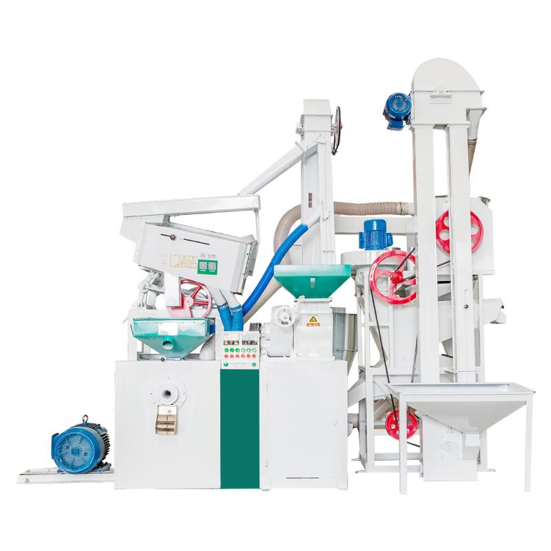
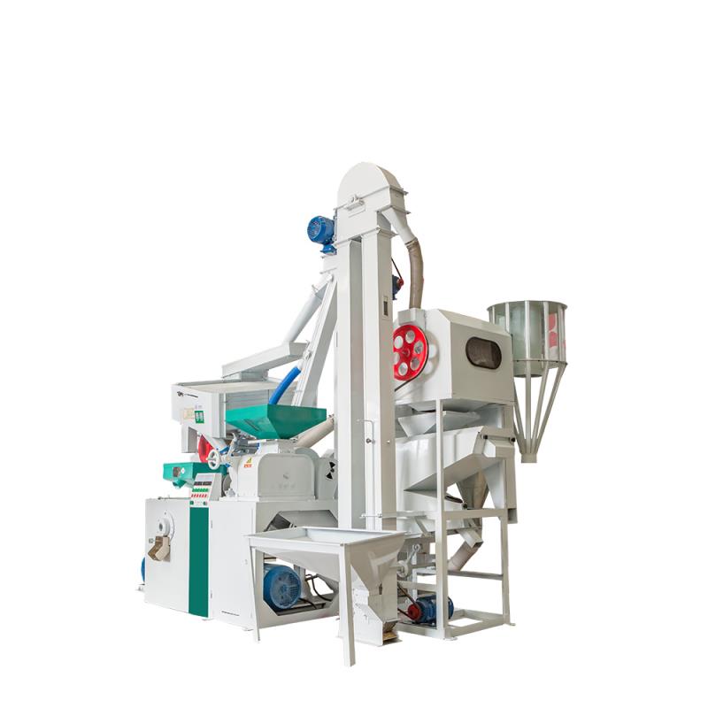
Rice Hulling Combination Rice Machine
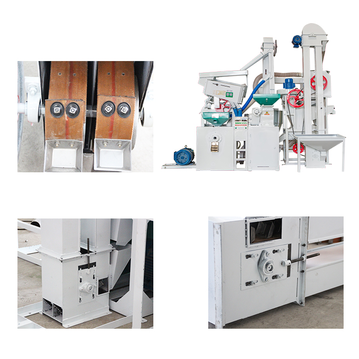
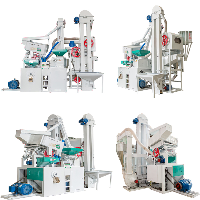
The combined rice husker has the advantages of low power, low energy consumption, large output, easy operation and good maintenance. The machine consists of a single-link elevator, a multifunctional cleaning and stone removing machine, a new split rice huller ( the core part of the equipment ), a double-link elevator, a grain rough separating screen, a negative pressure rice refining machine, a broken rice separating screen, a multifunctional crusher and a central centralized controller. The fuselage is made of wear-resistant glass pipes, which are durable and beautiful.
Equipment parameter:
| Equipment model | Rice output(kg/h) | Milled rice rate(%) | Weight of equipment(kg) | Equipment power(kw) | Dimension(L×W×H) | Power input(V/Hz) |
| MLNS15/15 | 500-700 | 69-75 | 1500 | 25 | 3200×1900×3000 | 380/50 |
Main characteristics of rice milling machine:
1. compact construction, beautiful appearance.
2. less broken rice increment.
3. easy to operate.
4. steady performance.
5. national patents.

MLNS 15/15 Rice Mill Machine,Efficient Rice Mill Machine,Rice Processing Machine,Wear Resistance Rice Mill Machine
Sichuan Doujin Technology Co., Ltd. , http://www.doujinmachine.com