Analysis of Application Error of Orifice Plate Flowmeter in Distribution Station
introduction
Natural gas metering is a dynamic, indirect and multi-parameter integrated metering. It is very difficult in the entire flow metering field and has the most influence factors. There are many types of flowmeters used in domestic natural gas trade settlement settlements, and the use of standard orifice flowmeters is the most widely used method. Due to the simple and robust structure of the orifice metering method, long service life, online replacement and overhaul, and high measurement accuracy, it has become an important measurement method for the settlement and settlement of natural gas trade, and is widely used in oil and gas fields.
1 Metering Status of Distribution Stations
Natural gas distribution stations are responsible for natural gas flow allocation and transmission and distribution tasks for urban residents. They need to be deployed according to the flow rate to meet the industrial and residential gas use at the peak and low peaks of gas use.
Combine the actual situation of the natural gas distribution team to improve the measurement accuracy of natural gas to reduce trade frictions. Natural gas metering at Shengli Oilfield's distribution stations mostly uses orifice flowmeters. The natural gas metering team of gas distribution team realized the automatic collection and processing of field data such as temperature, pressure and flow, display and report printing, realizing remote real-time monitoring and real-time data transmission, and achieved automatic operation of the whole measurement process.
Advanced orifice metering system consists of orifice valve, smart differential pressure transmitter , intelligent pressure transmitter , integrated temperature transmitter and flow calculation display device, including hardware and software. Its system structure topology is shown in Figure 1. 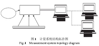
2 Orifice Flowmeter Measurement Error Analysis
The natural gas industry standard "Measurement of Natural Gas Flow Using Standard Orifice Flowmeters" (GB/T 21446) specifies the technical requirements, the internal structural forms, the pressure mode of orifice plates, the use of flowmeters, and calculations, uncertainties of standard orifice plates. The degree of data provides a standard basis for the measurement of natural gas orifice flowmeters. However, in practical applications, the accuracy of orifice flowmeters often fails to meet the requirements due to errors in the conditions of field use and errors in the meter itself. This paper analyzes the measurement error of orifice plate flowmeter from two aspects of basic error and additional error, and discusses the solution method.
2.1 Basic error
The basic error is an error determined by the accuracy of the metering device itself and is unavoidable. It is generally in the range of 1% to 2%. In order to standardize the orifice metering, "Technical Requirements for Natural Gas Metering System" (GB/T 18603) describes and requires the metering system. At the same time, the instrumentation and metering accuracy of the metering system is required.
The accuracy of the differential pressure transmitters, pressure transmitters, and temperature transmitters used in the orifice metering system of the gas distribution team of the base station is: 0.25%, 0.25%, and 0.5%, respectively, and meets the "Technical Requirements for Natural Gas Metering Systems" (GB). /T 18603) Accuracy requirements for B-grade system supporting instruments.
2.2 Additional errors
Combined with the field use situation, the following analysis will be conducted on the causes of additional errors in measurement.
2.2.1 The error caused by the deviation of the actual operation flow value from the design flow value
This is the most common and most concerned issue for gas distribution stations. Gas consumption has seasonal, daily, and hourly imbalances. Gas peaks and gas low peaks vary widely, and it is difficult to accurately grasp users' needs. The gas volume deviates greatly from the design flow rate.
If the maximum flow rate used to calculate the aperture of the orifice plate deviates from the actual maximum flow rate in the field, a larger deviation of the calculated aperture of the orifice will result. There is a problem of large orifices measuring small flow rates. Due to the small ΔP, the measurement accuracy is greatly reduced.
2.2.2 The error caused by the throttling device
1) Incorrect plate mounting causes measurement error. When installing the orifice plate in the orifice valve, it should be ensured that the orifice plate is installed in the correct direction and natural gas flows from the upper end face of the orifice plate to the lower end face. Table 3 shows the comparison between the total amount of gas supplied to the sampan and the total external gas supply. Under normal circumstances, the total amount of gas allocated for sewerage should be greater than the total external gas supply, as shown in Table 2 from 4.4 to 4.6. 4.6 The distribution of counters to the total wiring orifice plate was reversed. As a result, the total amount of gas supplied for the plutonium on the 4.7th day was less than that of the total outside distribution, causing a large error. 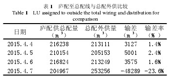
2) Measurement error due to inaccurate aperture plate size measurement. In actual use, because of the restriction of conditions, it cannot be sent to the verification department for verification in time. Instead, it is measured in the field with a vernier caliper. On the one hand, there is a visual error. On the other hand, because the calibration is not carried out under standard conditions, when the on-site environment and the temperature of the measuring medium are high, the aperture value of the measuring orifice will be too high, causing the measured value to be higher than the actual value. If the thickness of the orifice plate does not conform to the standard, the length of the upstream and downstream straight pipe segments is not enough, and the measurement device is installed improperly, it can cause measurement errors.
3) Measurement errors due to gas flushing and corrosion. Natural gas is extracted from the strata, and although it is separated and filtered, its components are very complex and its composition changes frequently. From a single well gas production measurement, gas gathering measurement to gas distribution measurement, the gas composition is different, so the flow meter In the process of use, it should be subject to the erosion and corrosion of the natural gas measured by the medium, and the erosion erosion of the orifice plate and the straight pipe section is particularly serious. This will affect the radius of the arc at the right angle of the orifice plate and the roughness of the inner surface of the straight pipe section, which will cause the outflow coefficient to change and the uncertainty of the measurement exceeds the expected value [2].
2.2.3 Differential Pressure Transmitter Induced Errors
Under the on-site environmental conditions, the pressure-conducting pipeline connected between the orifice plate flowmeter device and the differential pressure transmitter is prone to corrosion, blockage, freezing, etc., which is the key link of the orifice plate flowmeter and the key to its use and maintenance.
1) The zero point of differential pressure transmitter is easy to drift, resulting in distortion of static pressure and differential pressure, resulting in greater deviation of calculated gas volume than actual gas volume.
2) The differential pressure transmitter valve group and the pressure tube are liable to rust leak and block. Leakage or plugging of the high-pressure side and low-pressure side connections will cause large metering deviations.
During the maintenance of the Dongying Compressor Station in April 2015, the solids containing suspended particles and oil contained in the natural gas caused blockage of the downstream pressure conduits that were routed to the main distribution line, resulting in a large amount of metering data from the distribution lines to the total wiring.
2.2.4 Errors Caused by Changes in Natural Gas Components
Natural gas varies from single wells to gas-gathering stations and gas distribution stations with different temperamental components, so the flow values ​​are also different. On the one hand, because of the change in the relative density of natural gas due to changes in the gas composition, the natural gas flow rate is proportional to the square root of the inverse of the relative density. On the other hand, changes in the natural gas composition affect the calculation of the compression factor Z, resulting in an additional error in the compression factor, and the compression factor directly affects the flow rate of the flow into a unified standard. This shows that the change in natural gas composition has a great influence on the measurement.
In May 2015, sampling and analysis of the natural gas components at the junction of the smashing were performed again, and the contents of each component changed before and after the sampling analysis. From the calculation formula of relative density, the relative densities before and after sampling analysis are 0.6495 and 0.6425, respectively, which means that the relative density of natural gas changes by 1% before and after sampling analysis.
3 Measures to Improve the Measurement Accuracy of Orifice Flowmeters
The measurement accuracy of the orifice flowmeter is related to many factors such as orifice plate, pipeline conditions, installation quality, etc. To improve the accuracy of flow measurement, the following measures can be taken.
3.1 Manufacturing and Assembly of Orifice Flowmeters
The orifice plate's diameter, thickness, bevel, flow meter's shape, roughness, etc. shall meet the requirements of GB/T 2624.2. Flowmeter manufacturing and assembly must meet the requirements of GB/T 21446 and API MPMS 14.3.3. The sealing gasket of the orifice plate should be made of corrosion-resistant, anti-aging, and material that meets the temperature of the conveying medium. During assembly, it should be ensured that no point will protrude into the pipeline and the flow measurement accuracy will not be affected. There should be a good seal between the orifice plate and the guide plate between the upper and lower chambers.
Orifice flow meter manufacturing is the need to set the sewage valve and vent valve, emissions should be summarized as a total vent interface, unified emissions. The straight pipe section of the orifice flowmeter shall be determined according to the form of the process piping at the front and the rear of the orifice plate. Considering the certain margin factor, it is generally arranged in the first 30D after 15D [3].
3.2 Reasonable selection of measuring instruments
In order to avoid the errors caused by the phenomenon of "big horse-drawn cars" or "small horse-drawn carts", it is recommended to use the appropriate range instruments in strict accordance with the requirements of GB/T 18603 "Technical Requirements for Natural Gas Metering Systems." First of all, according to the gas flow, choose the inner plate of the inner diameter. Smart differential pressure transmitter range should be at full scale of 10% to 90%, smart pressure transmitter range should be 30% to 75% of full scale, it is best to use absolute pressure range instrument, the accuracy is recommended to use 0.1%.
3.3 Instrument Installation
Orifice flowmeters should be installed perpendicular to the axis of the pipe and concentric with the pipe. Deviations should be less than 1°. Orifice flowmeters should be provided with a mechanical device indicating orifice plate to test whether it is installed in the center of the pipe [4]. After the orifice plate is fixed between the flanges, it allows free thermal expansion without distortion. Under the condition of meeting the design pressure, the elastic deformation and plastic distortion caused by other forces or differential pressure should not exceed the linear inclination. 1%. The diameter of the pressure hole on the orifice plate is the same. The recommended diameter should be less than 13mm. The centerline of the pressure hole should be parallel to the ground and perpendicular to the centerline of the pipe. The deviation should not exceed 3°.
3.4 Strengthening measurement management, maintenance, and improvement of measurement rules and regulations
Strengthen the daily management and maintenance of the metering device, such as the periodic calibration of the pressure meter, if any abnormality or damage is found, it shall be repaired in a timely manner; in winter, the temperature will drop, and it will be easy to cause freezing and increase the number of discharges. Add to the differential pressure transmitter. Install insulation equipment; strengthen the orifice plate flow meter discharge and cleaning inspection, etc. [5]. Improve the rules and regulations for measurement, such as regular maintenance and periodic inspections. Strict management, so that metering device records, operating procedures, the use of a system, maintenance cycle.
3.5 Strengthen Business Training and Improve the Quality of Technical Staff
Strengthen the on-site operator's business training, improve the operator's technical level and ability to solve problems, and better do a good job of overhauling, maintaining and maintaining the flowmeter.
4 Conclusion
Orifice flow meters have been used in Shengli Oilfield for many years and play an irreplaceable role. At the same time, it can also improve working conditions, save manpower, increase the level of natural gas deployment and the operating efficiency of operators, and reduce production costs. Orifice flowmeter will be further optimized and improved in application, reduce errors and improve measurement accuracy
Brodifacoum pellets is a ready-to-use pellet bait. Highly platable formulation containing brodifacoum creating outstanding acceptance and effective control with a single feed. Brodifacoum pellets can be used in both rural and urban areas, including food industry, domestic and commercial premises. The pellets are best laid in bait trays and bait boxes in dry situations and environmentally-stable conditions.
Big Rat Killer,Brodifacoum Pellets,Brodifacoum Mouse Poison,Rat Poison With Brodifacoum
Liaoning Xinhe Technology Co.,Ltd. , https://www.bothpestcontrol.com