Application of 300MW Coal-Fired Unit Integration Control in Mawan Power Generating Plant
Shenzhen Mawan Power Generation Plant is the largest coal-fired power plant in Shenzhen with a total installed capacity of 4X300MW. The four units were connected to the grid for power generation in August 1993, January 1994, October 1996 and July 1997 respectively. Units 1 and 2 use the INFI-90 decentralized control system of Bailey Company of the United States. Units 3 and 4 use the PROCONTROL-P decentralized control system of ABB of Switzerland and implement the integration of machine, furnace and electricity for the domestic coal-fired unit units. Control, whether in the monitoring of the unit or in normal or accidental operation, faces the same system and uses a unified operating language.
1. Hosts and main auxiliary engines Mawan Power Plant has the same host and main auxiliary equipment for the four units. Among them, the boiler is the HG-1025/18.2-YM6 subcritical pressure, intermediate reheat and forced circulation drum boiler produced by the Harbin Boiler Works, with six HP medium speed coal mills, and the coal is Jinbei The bituminous coal adopts a four-corner arrangement of swing-type direct-flow burners to cut and burn in the park, and the coal fired under the MCR condition is 126.3t/h. The boiler has three layers of oil guns and uses No. 0 light diesel oil for ignition and low-load steady combustion. The maximum output of the oil system is designed according to 30% of the rated operating conditions of the boiler.
The steam turbine is a N300-16.7/537/537 type subcritical, primary intermediate reheat, high-medium pressure cylinder and single-shaft double-cylinder double-reverse steam reaction type condenser steam turbine produced by Harbin Steam Turbine Works. Turbine start adopts high-pressure main valve control mode; at 290r/min, high-pressure main valve and high-pressure control door are switched, and high-pressure control door is controlled to increase the speed and load mode. Each unit is equipped with two high pressure main valves, six high pressure control doors, two medium pressure main valves, and two medium pressure control doors.
The generator is manufactured by Harbin Electric Machinery Factory. The cooling method is water-hydrogen-hydrogen, and the excitation control introduces Westinghouse technology.
The unit is equipped with three feed pumps, one of which is an electric feed pump with a capacity of 50%, and two of which are each a steam feed pump with a capacity of 50%. In addition, a high- and low-voltage two-stage series bypass system with a capacity of 35% is also designed. The control system is the AV6 system of the Swiss company SULZER.
Second, the system architecture In the first phase of the project, the control system of two 300MW units in Mawan Phase 1 is the INFI-900 of Bailey Company of the United States. It has 3 loops in total, of which the #1 loop is the central ring of the whole plant and connects the control loops of all the units in the whole plant. Monitor and partially participate in the control of each unit; the #2 and #3 rings control the #1 and #2 units, respectively, and their hard and software configurations are exactly the same.
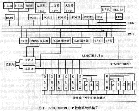
2. The control system of the two 300MW units in the second phase of Mawan Phase 2 is PROCONTROL-P of ABB Switzerland. Its hardware can be divided into two parts. The first part is the man-machine interface part MMI (MANMATION INTERFACE), which mainly includes four local area network LAN (POS), POSB, PMS, EDS and three bridges BRl2, BR61 and BR63 for connecting these four LANs. A server that connects the LAN to the remote bus of the PROCONTROL-P control system. On the POSA LAN, there is a hard copy machine HC01, three process control stations POS (PROCESS OPERATORSTATION), a large screen, and three on-line printers. There are two POS and two large screens on the POSB LAN. PMS (PLANTMANAGEMENTSYSTEM) Local Area Network (LAN) is a plant-wide management system that manages plant-wide data. EDS (ENGINEERINGDOCUMENTATIONANDSERVERS) has a large-scale workstation connected to the LAN. It is responsible for the software programming, fault diagnosis, and configuration file management of the P14 control system. The operating personnel operate the control system of the whole plant through five POSs. The maintenance engineer can diagnose the hardware and software faults of the control system through the fault diagnosis system CDS (CONTROLDIAGNOSTICS SYSTEM). Because LAN and PROCONTROL-P use different communication methods, they must establish contact with each other through the interface module. The second part is PROCONTROL-P control system, which includes two control parts P14 and P13. The P14 control part consists of more than 14 modular cabinets including DAS, SCS, CCS, BMS, and DEH/MEH. The functional processing station MPPS (MULTI-PURPOSE PROCESSSTATION) consists of. P13 is a protection and control system. It consists of a furnace safety monitoring system FSSS and a turbine protection and control system DEH/MEH. There are 4 control cabinets and 8 control stations. There is also a P13 system for programming, modification and fault diagnosis. Engineer Station EDS-P3. The specific structure is shown in Figure 1.
The software of the PROCONTROL-P control system consists of two parts. Part of the P14 control system, it has a special set of function code and programming protocol, which completes the plant's various systems of automatic control. Its software design is generally divided into functional group level and driver level. The function group level program is placed in the control module 83SR04. It mainly completes functions such as step sequence generation, device preselection, automatic/manual switching, etc.; In the corresponding drive control module, it mainly completes such functions as the control of the device, the feedback of the device state, the protection of the device, and the input and output of various signals. The software features of the P14 system are program decentralization, function decentralization, status of modules regardless of primary and secondary, and the normal operation of a large piece of equipment will not be affected by failure of a certain module during the control process, except for some important control loop functions of CCS. The redundant structure is set at the group level, and no redundant structure is provided at the rest. The other part is the P13 control system, which in turn has a special set of function codes and programming conventions that it uses to complete the FSSS and DEH/MEH functions. The hardware and software of the FSSS and DEH's protection part are designed using three-in-two logic, and they are programmed in negative logic. The protection uses the power-loss action method, and therefore the power supply is very demanding. The software design of P13 is different from that of P14. Its design mode is similar to that of BAILEY's INFI-90 system. The control modules are divided into main modules and input and output submodules. The programs are placed in the main module. Therefore, compared with P14, P13 has a low degree of dispersion, but because the protection is a three-by-two logic, the reliability is still very high.
The data in PROCONTROL-P is transmitted within the bus in the form of "telegraph code". Here the telegram code is derived from the telegram used by the post office. It also has an address and content, but its address is composed of the system number, station number, module number, register number, register number, etc. The standard telegram code consists of 71 bits. According to the different addresses, the telegraph code can be further divided into the source telegram code and the target telegraph code. The source telegram code indicates that the telegram is sent from this address. The telegram code indicates that the telegram code is sent to this address. The encoding principle of telegraph code is: the same signal has the same address anywhere. The telegram code is transmitted bit by bit in the bus and the transmission rate is IMB/s. If several MPPS stations transmit the telegram code to the remote bus at the same time, the data on the bus will be disorderly. In order to ensure the smooth transmission of the telegram code, there must be a management agency to manage the MPPS stations on the remote bus. This management agency is the main station (MASTERSTATION). In order to improve the reliability of communication, two remote buses are set in the system, and two master stations are used for management. When one bus fails, the other one will automatically take over. In order to realize the automatic relay function, a monitoring station (MONITORING STATION) is set up between the two master stations. A system can connect up to 250 MPPS stations, an MPPS station can connect up to 58 modules, and a module has 200 registers.
Third, the design overview Unit control software can be divided into five parts: data acquisition system (DAS), burner management system (BMS), closed-loop control system (CCS), sequential control system (SCS), steam turbine digital electro-hydraulic control system (DEH/MEH).
1. DAS system The DAS system mainly completes the collection and processing of the main and auxiliary signals of the unit such as pressure and temperature during the first phase of the project. In program design, the typical program structure used is that the signal is taken from the input channel of the computer and then sent to the superloop data channel through the exception report. After the operator interface unit (OIS) receives this information, it displays the corresponding value. On the display screen. The DAS system has the following typical features:
â— The normal display function of the process quantity;
â— High/low alarm display function of process quantity;
â— The recording function of the accident sequence.
In the recording function of sequential accidents, 160 switches of the main unit and auxiliary engine of the unit unit were monitored. Among them, there are 47 points on the boiler side, 38 on the turbine side, and 65 on the generator side.
In the second phase of the project, no independent DAS system was designed. The main functions of the DAS system are dispersed in other control systems. Its data processing is mainly completed by the power plant management system (PMS) on the network. It has more powerful data processing capabilities, richer content, and larger data storage capacity; it can completely replace the function of sequential recording, and it is more comprehensive and more specific and convenient for the analysis of accidents; the data is closely related to each other. The curve is also more intuitive.
2. The BMS system BMS system monitors and manages all the combustion equipment of the unit. Its main equipment consists of oil guns, fire detectors, coal mills, and oil-fired shut-off valves. The boiler has three layers of oil and six layers of coal. The BMS software consists of three parts: BMS common logic (FSSS), reservoir control logic, and coal control logic.
The BMS's common logic completes boiler purging condition confirmation, boiler purge process control, boiler ignition condition confirmation, boiler tripping protection interlock, and boiler trip out first state memory. The core content is the trip interlock logic of the boiler and its first-out memory.
BMS's reservoir control logic mainly completes the control and management of the 3-layer oil gun. Its function is reflected in the operation of the oil gun input/removal, the analysis of the oil gun operating status, and the control of the ignition gun input/removal.
The coal seam control logic primarily controls the six coal mills in sequence. The coal seam control logic completes the confirmation of coal seam input conditions, the sequential start/stop control of all the above-mentioned equipment of the coal mill unit, the status confirmation after the coal mill unit is put into operation, and the first-out memory of the reason for the coal mill trip.
The first stage BMS system consists of PCUI and PCU2. Each PCU contains 5 pairs of redundant MFPs, of which the common logic occupies a pair of MFPs. The FSSS function of the boiler is implemented in this MFP; each oil layer accounts for a total of three pairs of MFPs; Each seam accounts for a total of six pairs of MFPs. The MFT relays in the boiler protection logic are electrically active. The protection logic and hardware are single-channel. Only some of the important input signals use the three-input two. Compared with the second phase, the hardware structure and control logic of the first phase are relatively simple and clear.
The second stage BMS system consists of a P14 modular cabinet CBA06 and a relatively independent FSSS. The control strategy is hierarchical control. Most of the equipments in the BMS system adopt two-level control: functional group level and driver level. The function group level is responsible for completing the generation of automatic step sequences and pre-selection of equipment. The driver level is responsible for the execution of the step sequence and the equipment's own protection. Inform the function group level of the execution result to decide whether to execute the next step. If a failure occurs at the functional group level, it will not affect the normal operation of the drive level equipment. The operating personnel can control the equipment in the drive level directly from the POS.
FSSS consists of a P13 modular cabinet CBA07, which includes three channels A, B, and C. The hardware and software structures of these three channels are the same. They are composed of the main module and the input and output submodules. All the analog and digital quantities are sent to the three channels for the same processing. Channels use serial communication for data exchange. The three channels exchange information with P14 through the communication module groups 88QT03, 88QB03, and 70BT01. The communication mode is still in the form of a telegraph code. From the perspective of the BMS system, the three channels of the FSSS can be considered as its three independent integrated input/output modules. The connection to the BMS station bus is shown in Figure 2.
The FSSS completes the control of the fuel shut-off valve and the MFT relay. The MFT relay is in the de-energized mode. All signals entering the FSSS system take the form of three to two. The programming of the FSSS system is done by EDS-P3, using negative logic for programming. MFT takes three parts of the action circuit shown in Figure 3. In order to ensure the reliability of the protection system, the FSSS system is designed with a periodic self-check function, and periodically performs self-tests on sensors, auxiliary power, input modules, output modules, processing modules, trip circuits and data transmission in the system.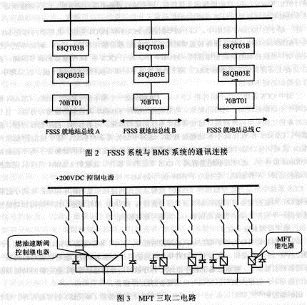
3. Closed-loop control system (CCS)
There are 61 sets of control loops for the closed-loop control system, completing the control of 65 actuators. The control software of the CCS system is mainly divided according to the control network. The contents are divided into: coordinated control loop, machine-to-furnace control loop, furnace control loop, AF coal feeder speed control loop, A-F mill Outlet temperature control loop, AF mill primary air flow control loop, AF mill fuel air control loop, blower A/B air volume control loop, furnace negative pressure control loop, flue gas oxygen control loop, steam feed water pump A/B Speed ​​control loop, feedwater start valve differential pressure control loop, superheated steam first-degree temperature reduction control loop, superheated steam two-level desuperheating control loop, reheat steam injection water temperature desuperheating control loop, condenser water level control loop, three sets Water supply pump sealed water differential pressure control circuit, deaerator water level control circuit, auxiliary steam pressure control loop for deaerator, boiler fuel flow control loop, atomized steam pressure control loop, AB/CD/EF secondary air pressure control loop , Burner angle control loop, auxiliary steam header pressure control loop, etc.
In the above control loop, the software design is functionally divided into signal selection and quality detection, formation of a closed-loop loop, interlocking with the status of auxiliary equipment, abnormal alarming during process control, calculation of basic fixed-value configuration, and operation from The normal offset and hand/automatic handoff tracking performed at the operator station will automatically allocate the load of the same auxiliary equipment. These functions ensure that the closed-loop system maintains correctness of normal operation of the unit.
In the first stage of two 300MW units, the above control loop is completed by PCU3 and PCU4. The distribution principle of the configuration content in the MFP is function decentralization, that is, the configurations of the more important control loops are dispersed in each controller. For example, the functions of the drum level control and the combustion control are not arranged in the same pair of MFPs. For the 44 important adjustment loops in CCS, there is also a standby manual operation station SAC on the BTG vertical plate, which is used for the hard manipulation of the adjustment actuator in special circumstances. In the second phase, there was no similar hard-hand station.
The second phase CCS system consists of two modular cabinets CBA04, CBA05 and a terminal cabinet CVA05. There are two multi-function processing stations in the CBA04 cabinet. Use the powerful intelligent control module 83SR07 to decentralize the control function and connect the control object to the standard wiring. This makes the structure of the entire system clear, high reliability, convenient fault finding and easy maintenance. The CBA05 cabinet contains two multi-function processing stations. The two stations are redundant control stations. Each station consists of a control module 83SR04 and a communication interface module. The control software of the important control loop in the CCS system is loaded in the 83SR04 module of the two control stations at the same time. This redundant configuration improves the reliability of the CCS system. The 83SR04 module here only performs the operation of the control strategy and is not driven. It is equivalent to the MFP module in INFI-90.
The intelligent control module 83SR07 used in the CCS system can independently complete the closed-loop control of two analog quantities. There are two process unit interfaces. The control and feedback signals related to the controlled equipment are directly connected to the 83SR07 module. This decentralization of structure and function makes the impact of a single module fault smaller and the system more reliable.
4. Sequence Control System (SCS)
The sequential control function components are two parts of boiler sequence control and steam turbine sequence control. Among them, there are 15 function groups for boiler sequence control and 20 function buttons for steam engine sequence control. The SCS control software structure takes the function group as the basic unit, and can complete the direct operation of a specific device in the group, the start/stop of the entire group of device programs, the display of the cause of the program failure, and so on. Under the guidance of the complete function help screen, the operator can complete the start/stop operation of the function device.
There are 35 functional groups for boiler sequential control and turbine control, and no higher-level (unit-level) management program has been designed. Each functional group is independent in the control relationship, and the functional groups in the production process have signal connections only on the interlock signal interface of the functional group. Therefore, SCS is only designed to the functional group level, and there is no higher-level unit self-start/stop program as the management program for these functional groups.
The first-phase sequential control system is completed by PCU5, PCU6, PCU7, PCU8. The 15 function groups of the boiler control are held in PCU5 and part of PCU6. The 20 function groups of steam turbine sequence control are arranged in another part of PCU6 and PCU7. , PCU8. When there are parallel running equipments in the thermal system, such as sending, draught fan, primary air blower, air preheater, etc., the control configuration is arranged in different MFPs. The input and output signals corresponding to each device are also arranged in the corresponding MFP. Submodules. For each sequence group, its hardware and software design patterns are the same. It mainly includes multi-function processing modules, digital input modules, digital output modules, and intermediate relay cabinets. The feedback signal is input through the terminal board system, and the control command is output through the intermediate relay.
The second-phase sequential control system consists of two modular cabinets CBA02, CBA03, four intermediate relay cabinets CTE01, CTE02, CTE03, CTE04, and a terminal cabinet CVA04. There are two multi-function processing stations in each module cabinet. All control commands are output through the intermediate relay cabinet. The main control module 83SR04 used in the sequential control system is a very powerful intelligent control module. It can not only complete the drive level switching and analog control, but also store the function group control configuration. Each 83SR04 module has four drive interfaces. In the sequential control system, four sequence control devices can be controlled. The drive interface part is a standardized design, that is, each drive interface has two control outputs: on/off or off/stop; four-way status feedback signal input: MCC fault (STA), torque switch (MFO), device status signal on/ OPEN/ONorCLOSED/OFF. The two control outputs are 24V. DC active control commands; four-way status feedback signals are all normally open contact signals, provided by the module all the way 48V. DC power supply.
5. Turbine Digital Electrohydraulic Control System (DEH/MEH)
The first-phase DEH control system was designed and manufactured by the ETSI company under ELSAGBAILEY GROUP. Mawan Power Plant is the first power plant in China to use the company's DEH control system. Its electronic control part functions as follows:
On the loop, DEH occupies #13PCU, there are a total of 8 master modules, of which 3 pairs of redundant master modules execute speed control, automatic control and manual control respectively, one master module performs self-start control, and one master module serves as a rotor. Stress calculations. In addition to the OIS station, the DEH is also equipped with an auxiliary operating panel mounted on the operator's station as a back-up manual control. In addition to the normal operations such as lifting/unloading of load/speed, selection of various operating modes, and self-starting, DEH can also perform Emergency manual operation, which is a function that cannot be implemented on the OIS station.
The speed control part has three-speed, two-select logic, 103% and 110% electrical overspeed protection, load imbalance protection and trip signal output. Therefore, the main module is required to have a faster operation speed, and the scanning period of the module is 0.05 seconds. The automatic control part is equipped with speed/load control and its associated acceleration/loading ratio, configuration of high and low limits, selection of each control loop, switching logic of main/speed control valves, and other system interfaces. The manual control part mainly completes the valve control such as valve manual control, valve test, valve verification, single valve-sequence valve conversion, valve emergency manual, etc., and resident valve curve. The start-up control section can complete the automatic detection of each step from the rolling stock to the grid connection. The overriding function provided provides a flexible operation mode, in which the operator decides whether or not to over-ride a sensor that may not be concerned about the possible fault of the alarm. The rotor stress part calculates the average temperature of the rotor surface, inner bore wall and rotor volume based on the steam and metal temperatures at the typical cross section, and calculates the stress coefficient to determine whether it is necessary to correct the speed increase/liter load rate to obtain the time required for warming up. As well as the allowable range of main steam and reheat steam temperatures at the current rotor temperature.
In addition to the MEH system does not have a self-starting program and stress calculation program, the design concept of its manual and automatic control program is similar to that of DEH, and will not be repeated here.
Phase II DEH/MEH, as part of the DCS system of the unit, uses a newly developed general-purpose digital control system made of PROCONTROLP13 from ABB. Divided by function, DEH/MEH control system can be divided into two parts: safety protection part and control part. DEH's security protection consists of three protection channels. The control part consists of a basic controller and an automatic controller. The MEH security protection system consists of two protection channels. The DEH/MEH system consists of five control stations A, B, C, D, E and one P14 communication interface module cabinet CBA08. Station A and Station D are located in the CBA09 Modular Cabinet. Station A is composed of digital input/output modules, analog input modules, communication modules, and main control modules. It is equipped with a turbine protection channel A, a small turbine A protection channel A, and a small turbine B protection channel A configuration. Corresponding protection function. Station B and station E are located in the CBAl0 modular cabinet. The structure of station B is exactly the same as that of station A. It is configured to protect the configuration of the turbine protection channel B, the small turbine A protection channel B, and the small turbine B to complete the corresponding protection function. Station C is located in the CBAII modular cabinet, which consists of a switch input/output module, an analog input/output module, a communication module, a speed input module, and a main control module. It is equipped with a turbine protection channel C and two basic controls. , two automatic controllers, stress calculation, strobe gate, test configuration, complete the corresponding protection and control management functions. Station D is the controller of the small turbine A, which consists of a switch input/output module, an analog input/output module, a communication module, a speed input module, and a main control module. Station E is the controller of small steam turbine B, and its structure is exactly the same as station D. The three control stations A, B and C complete the information exchange through the serial communication interface module. The communication between the five control stations and the unit control system P14 is completed through the interface cabinet CBA08, as shown in Fig. 4.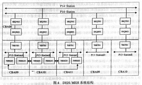
The turbine protection system uses three-selection two logic in software and hardware. Protection is divided into A, B, C three channels. The three-channel software configuration is basically the same, using negative logic to design. Each channel controls a high and low voltage trip Solenoid Valve. Three high- and low-voltage tripping solenoid valves can cause tripping of the turbine if there are two controlled loss of power at the same time.
The turbine control system includes two basic controllers (BC) and two automatic controllers (AC). The software configuration of the two basic controllers is exactly the same, and they are loaded in two control master modules 70PR05. The two basic controllers work one and the other is standby and can realize bumpless switching automatically. The configurations of the two automatic controllers are also identical, and they are loaded in two control master modules 70PR05. Two automatic controllers work one and one standby, and can realize bumpless switching automatically. The basic controller is the foundation. Automatic controllers can be used only when the basic controller is in good condition. When the automatic controller is faulty, it will automatically return to the basic controller.
Basic controllers mainly include speed control and load control. Speed ​​control is PI closed-loop control and load control is open-loop control. When the basic controller is working alone, the operator can manually control the whole process of the turbine from hanging brakes, rushing, warming up, simultaneous grid-connect, to initial load, and full load. The speed and load set points are manually given by the operating personnel. Out. After entering the automatic controller, the speed and load setpoints are given by the automatic controller.
The automatic controller is a kind of advanced controller, which can complete the automatic start of the turbine and the whole process of the automatic load according to the stress of the steam turbine. According to the different stress, it can automatically choose different lifting rate or loading rate. Automatic controllers mainly include startup programs and load programs. The rotational speed set by the start-up program is directly output to the basic controller; the load setpoint formed by the load program is corrected by the limiter and the additional controller and sent to the basic controller. There are three PI-type additional controllers in the automatic controller; main steam pressure controller (TFB), power controller (BFT) and pressure controller. The output signal of the additional controller replaces the output value of the load program and is sent to the basic controller. When an additional controller is selected, the other two additional controllers and the load program are automatically in tracking mode to achieve bumpless switching between various controllers.
There are two kinds of limiters in the automatic controller: level pressure limiter and load RUNBACK. The limiter's minimum output value is the upper limit of the automatic controller load setpoint. When the limiter is active, all additional controllers exit and the load setpoints of the additional controller and automatic controller are in a tracking mode to ensure bumpless switching in restricted and unrestricted modes.
The MEH protection system employs dual redundant logic in both software and hardware. The protection is divided into two channels, A and B. The software configurations of the two channels are basically the same and negative logic is used for design. Each channel controls a high- and low-voltage tripping solenoid valve. If there is a controlled loss of power in two high- and low-voltage tripping solenoid valves, it will cause the small turbine to trip. The main task of the MEH is to perform closed-loop control of the rotational speed of the driven water pump turbine. According to the different speed setting modes, it can be divided into three control modes: manual control, automatic control and remote water supply control. In different control modes, there are different speed control ranges. In manual control, the speed set point is given by the operator from the manual or POS terminal, the control range is 0~5750rpm; in automatic control, the target speed is 3000rpm. According to the actual speed of the steam turbine, the MEH selects different lift rates and finally controls the speed at 3000 rpm. When the speed of the driven water pump turbine reaches 3000 rpm, remote feedwater control can be used. The target speed of the remote water supply control is given by the CCS system, and the control range is 3000~5750 rpm.
Fourth, system characteristics 1. Rich shared operating interface resources The INFI-90 system's human-machine interface is mainly composed of OIS. The BTG disk is an auxiliary operation interface. When the unit is running normally, it does not implement the integrated control strategy on the BTG disk. OIS rich operation Surface resources can be shared for boiler control, turbine control, and electrical control.
The OIS has a total of 263 operating screens, which can be divided into seven categories according to their completed functions. They are:
â— There are four main menu screens, which are BMS, CCS, SCS, and DEH main menus.
â— Production process system various types of pictures (also known as dynamic maps);
â— The function group starts/stops the help screen;
â— process volume alarm screen;
â— performance calculation window class screen;
â— Process volume report type screen.
The above pictures are completely designed according to the professional characteristics of the power production. The operating personnel can quickly understand the current equipment status during use. During this time, nearly 10,000 points of information are collected and the overall awareness of the unit is strengthened.
2. After the unified information processing standard unit adopts the same type of computer to implement control, the processing standards of I/O information have been unified, and uniform quality inspection specifications have been adopted for data entry. According to the characteristics and needs of the actual production process, a unified single-point input standard processing program, dual-point input standard processing program, and three-point input standard program are designed to improve the standardization of software design. On the output side of the signal, 24V is used uniformly. DC contact output and 4-20mA standard current output ensure the consistency of the signal device in the controlled device.
3. Reasonable allocation process processing time Due to the differences in the characteristics of the boiler control object and the turbine control object itself, there is no strict requirement for the execution time of the boiler control object program. In the execution time of not more than 1 second, the control of the boiler equipment can be guaranteed. Claim. Because the turbine's speed flying characteristic itself requires that the computer that bears the part control does not consume too much energy when completing a program scan, the length of the program can be reasonably allocated, and the extra programs that are not related to the overspeed protection are placed on other multi-function controllers. Go to. The program execution time of the overspeed protection part of the steam turbine is designed to be only 0.04524 seconds, which fully satisfies the requirements for overspeed protection control of the turbine main and speed control valves.
4. Unified configuration modification and system maintenance The INFI-90 system is configured with function codes. At present, nearly 200 function codes have been developed. When configuring, users only need to combine function codes according to their own needs and fill in specification parameters. The configuration is convenient and there are no language clauses. INFI-90 system has the means of online configuration, can be modified online on the redundant main module according to the need of operation, and can switch the control module without disturbance. If the modification is not suitable, the original configuration can be restored at any time, which is extremely convenient user.
When the INFI-90 system maintains the control software, there are three available configuration tools, ie, EWS, CTM, and OIS. There are two kinds of configuration methods adopted, one of which is that the configuration map software is compiled and then downloaded to the MEP. The compilation process is completed in the EWS. The second is to directly enter the function code. Therefore, the above-mentioned maintenance tool can perform system maintenance on any part within the control range of INFI-90, and it is not necessary to re-master the operation of a new computer system.
5. The special communication agreement between the furnaces ensures that there is no interface problem in the entire system. All data in the entire DCS system can be shared, and there are no interface problems of data transmission between several different types of controllers. Because the super-ring adopts a dual-ring redundant structure and the communication speed is 10 MB, the data transmission is reliable, and the communication between different PCUs is completed by the super-loop except for the extremely important machine-rail interlock signal that is transmitted by the super-loop, thereby greatly simplifying The scale of the interface between control systems can save a lot of cables.
6.100% CRT operation and monitoring functions Due to the integrated control strategy, all the main and auxiliary equipments of boilers, turbines and generators can be operated on the same five CRTs. BTG discs are equipped with operators for important equipment such as oil guns and pulverizers. When using exactly the same type of 7 screens, there is no mutual translation of the same information, which greatly increases the information usage rate and speed. Reducing the labor intensity of operations personnel and increasing the speed of response to accidents are helpful.
7.100% of the fault diagnosis function As the computer network adopts a unified operation mode, first of all, it guarantees that the machine, furnace, and electric operation have completely consistent operation records. In addition, the same information processing standards, the same first-out screen design, and alarms all provide the basis for the diagnosis of the operational status of the crew. Sequential events: After the recorder's print results are combined with the above information, the INFI-90 system takes 100% of the work to analyze the accident.
8. Good control function development prospects Control software always has its flaws. However, after the computer hardware is unified, it establishes the foundation for the development of control functions. For example, the entire unit can be developed for the same type of control system, starting with the start/stop process and the entire unit's performance calculations. No new hardware additions are involved, reducing the technical difficulty of the development work.
V. Operation of the system (1) The overall reliability of the DCS system is high, the functions are complete, and the operation is convenient and flexible. Since the commissioning of the machine on July 3, 1996, there has been no tripping accident caused by the failure of the DCS system itself. However, the P14 control system for SCS, CCS, and DAS is slightly higher than the P13 control system for FSSS and DEH/MEH. The 16-channel signal input module in the P14 system has experienced a situation in which one of the channels is bad, and since the signal input channel is not backed up, a module needs to be replaced when a channel is damaged. However, since the P13 system has been operating so far, no module failure has occurred.
(2) SCS and CCS systems have a high degree of dispersion. A functional module only completes 1 or 2 control loops or 1-4 devices. Due to the high degree of dispersion, the damage of a functional module has little effect on the system. The interface between the driver stage of the functional module and the controlled device adopts a standard connection, which is very convenient and quick when dealing with faults or solving problems.
(3) The DEH/MEH system not only has a control function but also a protection function. Most of DEH's design features can be achieved. DEH's performance calculation program has not been applied since ABB did not commission it. The protection part applies the principle of power failure tripping, and therefore has a high requirement for the reliability of the control power supply.
(4) The DCS system includes two parts, P13 and P14. The modules used by P13 and P14 are different. The programming function codes are different, and each has a dedicated engineer workstation. The operation method of the engineer workstation is also different. The application of two types of systems not only increases the communication interface problems of various parts, but also increases the types and quantities of spare parts, and increases the workload of thermal maintenance personnel.
(5) DCS system power supply circuit not only requires high reliability, but also requires guarantee of power supply quality. There was an accident that the DCS system was out of control due to power supply voltage fluctuations during operation.
The actual operation shows that the application of the PROCONTROL-P control system in the western power plant is successful. The control system has high reliability and rich functions, and can meet the requirements of monitoring and control of large-scale thermal power units.
1. Hosts and main auxiliary engines Mawan Power Plant has the same host and main auxiliary equipment for the four units. Among them, the boiler is the HG-1025/18.2-YM6 subcritical pressure, intermediate reheat and forced circulation drum boiler produced by the Harbin Boiler Works, with six HP medium speed coal mills, and the coal is Jinbei The bituminous coal adopts a four-corner arrangement of swing-type direct-flow burners to cut and burn in the park, and the coal fired under the MCR condition is 126.3t/h. The boiler has three layers of oil guns and uses No. 0 light diesel oil for ignition and low-load steady combustion. The maximum output of the oil system is designed according to 30% of the rated operating conditions of the boiler.
The steam turbine is a N300-16.7/537/537 type subcritical, primary intermediate reheat, high-medium pressure cylinder and single-shaft double-cylinder double-reverse steam reaction type condenser steam turbine produced by Harbin Steam Turbine Works. Turbine start adopts high-pressure main valve control mode; at 290r/min, high-pressure main valve and high-pressure control door are switched, and high-pressure control door is controlled to increase the speed and load mode. Each unit is equipped with two high pressure main valves, six high pressure control doors, two medium pressure main valves, and two medium pressure control doors.
The generator is manufactured by Harbin Electric Machinery Factory. The cooling method is water-hydrogen-hydrogen, and the excitation control introduces Westinghouse technology.
The unit is equipped with three feed pumps, one of which is an electric feed pump with a capacity of 50%, and two of which are each a steam feed pump with a capacity of 50%. In addition, a high- and low-voltage two-stage series bypass system with a capacity of 35% is also designed. The control system is the AV6 system of the Swiss company SULZER.
Second, the system architecture In the first phase of the project, the control system of two 300MW units in Mawan Phase 1 is the INFI-900 of Bailey Company of the United States. It has 3 loops in total, of which the #1 loop is the central ring of the whole plant and connects the control loops of all the units in the whole plant. Monitor and partially participate in the control of each unit; the #2 and #3 rings control the #1 and #2 units, respectively, and their hard and software configurations are exactly the same.
2. The control system of the two 300MW units in the second phase of Mawan Phase 2 is PROCONTROL-P of ABB Switzerland. Its hardware can be divided into two parts. The first part is the man-machine interface part MMI (MANMATION INTERFACE), which mainly includes four local area network LAN (POS), POSB, PMS, EDS and three bridges BRl2, BR61 and BR63 for connecting these four LANs. A server that connects the LAN to the remote bus of the PROCONTROL-P control system. On the POSA LAN, there is a hard copy machine HC01, three process control stations POS (PROCESS OPERATORSTATION), a large screen, and three on-line printers. There are two POS and two large screens on the POSB LAN. PMS (PLANTMANAGEMENTSYSTEM) Local Area Network (LAN) is a plant-wide management system that manages plant-wide data. EDS (ENGINEERINGDOCUMENTATIONANDSERVERS) has a large-scale workstation connected to the LAN. It is responsible for the software programming, fault diagnosis, and configuration file management of the P14 control system. The operating personnel operate the control system of the whole plant through five POSs. The maintenance engineer can diagnose the hardware and software faults of the control system through the fault diagnosis system CDS (CONTROLDIAGNOSTICS SYSTEM). Because LAN and PROCONTROL-P use different communication methods, they must establish contact with each other through the interface module. The second part is PROCONTROL-P control system, which includes two control parts P14 and P13. The P14 control part consists of more than 14 modular cabinets including DAS, SCS, CCS, BMS, and DEH/MEH. The functional processing station MPPS (MULTI-PURPOSE PROCESSSTATION) consists of. P13 is a protection and control system. It consists of a furnace safety monitoring system FSSS and a turbine protection and control system DEH/MEH. There are 4 control cabinets and 8 control stations. There is also a P13 system for programming, modification and fault diagnosis. Engineer Station EDS-P3. The specific structure is shown in Figure 1.
The software of the PROCONTROL-P control system consists of two parts. Part of the P14 control system, it has a special set of function code and programming protocol, which completes the plant's various systems of automatic control. Its software design is generally divided into functional group level and driver level. The function group level program is placed in the control module 83SR04. It mainly completes functions such as step sequence generation, device preselection, automatic/manual switching, etc.; In the corresponding drive control module, it mainly completes such functions as the control of the device, the feedback of the device state, the protection of the device, and the input and output of various signals. The software features of the P14 system are program decentralization, function decentralization, status of modules regardless of primary and secondary, and the normal operation of a large piece of equipment will not be affected by failure of a certain module during the control process, except for some important control loop functions of CCS. The redundant structure is set at the group level, and no redundant structure is provided at the rest. The other part is the P13 control system, which in turn has a special set of function codes and programming conventions that it uses to complete the FSSS and DEH/MEH functions. The hardware and software of the FSSS and DEH's protection part are designed using three-in-two logic, and they are programmed in negative logic. The protection uses the power-loss action method, and therefore the power supply is very demanding. The software design of P13 is different from that of P14. Its design mode is similar to that of BAILEY's INFI-90 system. The control modules are divided into main modules and input and output submodules. The programs are placed in the main module. Therefore, compared with P14, P13 has a low degree of dispersion, but because the protection is a three-by-two logic, the reliability is still very high.
The data in PROCONTROL-P is transmitted within the bus in the form of "telegraph code". Here the telegram code is derived from the telegram used by the post office. It also has an address and content, but its address is composed of the system number, station number, module number, register number, register number, etc. The standard telegram code consists of 71 bits. According to the different addresses, the telegraph code can be further divided into the source telegram code and the target telegraph code. The source telegram code indicates that the telegram is sent from this address. The telegram code indicates that the telegram code is sent to this address. The encoding principle of telegraph code is: the same signal has the same address anywhere. The telegram code is transmitted bit by bit in the bus and the transmission rate is IMB/s. If several MPPS stations transmit the telegram code to the remote bus at the same time, the data on the bus will be disorderly. In order to ensure the smooth transmission of the telegram code, there must be a management agency to manage the MPPS stations on the remote bus. This management agency is the main station (MASTERSTATION). In order to improve the reliability of communication, two remote buses are set in the system, and two master stations are used for management. When one bus fails, the other one will automatically take over. In order to realize the automatic relay function, a monitoring station (MONITORING STATION) is set up between the two master stations. A system can connect up to 250 MPPS stations, an MPPS station can connect up to 58 modules, and a module has 200 registers.
Third, the design overview Unit control software can be divided into five parts: data acquisition system (DAS), burner management system (BMS), closed-loop control system (CCS), sequential control system (SCS), steam turbine digital electro-hydraulic control system (DEH/MEH).
1. DAS system The DAS system mainly completes the collection and processing of the main and auxiliary signals of the unit such as pressure and temperature during the first phase of the project. In program design, the typical program structure used is that the signal is taken from the input channel of the computer and then sent to the superloop data channel through the exception report. After the operator interface unit (OIS) receives this information, it displays the corresponding value. On the display screen. The DAS system has the following typical features:
â— The normal display function of the process quantity;
â— High/low alarm display function of process quantity;
â— The recording function of the accident sequence.
In the recording function of sequential accidents, 160 switches of the main unit and auxiliary engine of the unit unit were monitored. Among them, there are 47 points on the boiler side, 38 on the turbine side, and 65 on the generator side.
In the second phase of the project, no independent DAS system was designed. The main functions of the DAS system are dispersed in other control systems. Its data processing is mainly completed by the power plant management system (PMS) on the network. It has more powerful data processing capabilities, richer content, and larger data storage capacity; it can completely replace the function of sequential recording, and it is more comprehensive and more specific and convenient for the analysis of accidents; the data is closely related to each other. The curve is also more intuitive.
2. The BMS system BMS system monitors and manages all the combustion equipment of the unit. Its main equipment consists of oil guns, fire detectors, coal mills, and oil-fired shut-off valves. The boiler has three layers of oil and six layers of coal. The BMS software consists of three parts: BMS common logic (FSSS), reservoir control logic, and coal control logic.
The BMS's common logic completes boiler purging condition confirmation, boiler purge process control, boiler ignition condition confirmation, boiler tripping protection interlock, and boiler trip out first state memory. The core content is the trip interlock logic of the boiler and its first-out memory.
BMS's reservoir control logic mainly completes the control and management of the 3-layer oil gun. Its function is reflected in the operation of the oil gun input/removal, the analysis of the oil gun operating status, and the control of the ignition gun input/removal.
The coal seam control logic primarily controls the six coal mills in sequence. The coal seam control logic completes the confirmation of coal seam input conditions, the sequential start/stop control of all the above-mentioned equipment of the coal mill unit, the status confirmation after the coal mill unit is put into operation, and the first-out memory of the reason for the coal mill trip.
The first stage BMS system consists of PCUI and PCU2. Each PCU contains 5 pairs of redundant MFPs, of which the common logic occupies a pair of MFPs. The FSSS function of the boiler is implemented in this MFP; each oil layer accounts for a total of three pairs of MFPs; Each seam accounts for a total of six pairs of MFPs. The MFT relays in the boiler protection logic are electrically active. The protection logic and hardware are single-channel. Only some of the important input signals use the three-input two. Compared with the second phase, the hardware structure and control logic of the first phase are relatively simple and clear.
The second stage BMS system consists of a P14 modular cabinet CBA06 and a relatively independent FSSS. The control strategy is hierarchical control. Most of the equipments in the BMS system adopt two-level control: functional group level and driver level. The function group level is responsible for completing the generation of automatic step sequences and pre-selection of equipment. The driver level is responsible for the execution of the step sequence and the equipment's own protection. Inform the function group level of the execution result to decide whether to execute the next step. If a failure occurs at the functional group level, it will not affect the normal operation of the drive level equipment. The operating personnel can control the equipment in the drive level directly from the POS.
FSSS consists of a P13 modular cabinet CBA07, which includes three channels A, B, and C. The hardware and software structures of these three channels are the same. They are composed of the main module and the input and output submodules. All the analog and digital quantities are sent to the three channels for the same processing. Channels use serial communication for data exchange. The three channels exchange information with P14 through the communication module groups 88QT03, 88QB03, and 70BT01. The communication mode is still in the form of a telegraph code. From the perspective of the BMS system, the three channels of the FSSS can be considered as its three independent integrated input/output modules. The connection to the BMS station bus is shown in Figure 2.
The FSSS completes the control of the fuel shut-off valve and the MFT relay. The MFT relay is in the de-energized mode. All signals entering the FSSS system take the form of three to two. The programming of the FSSS system is done by EDS-P3, using negative logic for programming. MFT takes three parts of the action circuit shown in Figure 3. In order to ensure the reliability of the protection system, the FSSS system is designed with a periodic self-check function, and periodically performs self-tests on sensors, auxiliary power, input modules, output modules, processing modules, trip circuits and data transmission in the system.
3. Closed-loop control system (CCS)
There are 61 sets of control loops for the closed-loop control system, completing the control of 65 actuators. The control software of the CCS system is mainly divided according to the control network. The contents are divided into: coordinated control loop, machine-to-furnace control loop, furnace control loop, AF coal feeder speed control loop, A-F mill Outlet temperature control loop, AF mill primary air flow control loop, AF mill fuel air control loop, blower A/B air volume control loop, furnace negative pressure control loop, flue gas oxygen control loop, steam feed water pump A/B Speed ​​control loop, feedwater start valve differential pressure control loop, superheated steam first-degree temperature reduction control loop, superheated steam two-level desuperheating control loop, reheat steam injection water temperature desuperheating control loop, condenser water level control loop, three sets Water supply pump sealed water differential pressure control circuit, deaerator water level control circuit, auxiliary steam pressure control loop for deaerator, boiler fuel flow control loop, atomized steam pressure control loop, AB/CD/EF secondary air pressure control loop , Burner angle control loop, auxiliary steam header pressure control loop, etc.
In the above control loop, the software design is functionally divided into signal selection and quality detection, formation of a closed-loop loop, interlocking with the status of auxiliary equipment, abnormal alarming during process control, calculation of basic fixed-value configuration, and operation from The normal offset and hand/automatic handoff tracking performed at the operator station will automatically allocate the load of the same auxiliary equipment. These functions ensure that the closed-loop system maintains correctness of normal operation of the unit.
In the first stage of two 300MW units, the above control loop is completed by PCU3 and PCU4. The distribution principle of the configuration content in the MFP is function decentralization, that is, the configurations of the more important control loops are dispersed in each controller. For example, the functions of the drum level control and the combustion control are not arranged in the same pair of MFPs. For the 44 important adjustment loops in CCS, there is also a standby manual operation station SAC on the BTG vertical plate, which is used for the hard manipulation of the adjustment actuator in special circumstances. In the second phase, there was no similar hard-hand station.
The second phase CCS system consists of two modular cabinets CBA04, CBA05 and a terminal cabinet CVA05. There are two multi-function processing stations in the CBA04 cabinet. Use the powerful intelligent control module 83SR07 to decentralize the control function and connect the control object to the standard wiring. This makes the structure of the entire system clear, high reliability, convenient fault finding and easy maintenance. The CBA05 cabinet contains two multi-function processing stations. The two stations are redundant control stations. Each station consists of a control module 83SR04 and a communication interface module. The control software of the important control loop in the CCS system is loaded in the 83SR04 module of the two control stations at the same time. This redundant configuration improves the reliability of the CCS system. The 83SR04 module here only performs the operation of the control strategy and is not driven. It is equivalent to the MFP module in INFI-90.
The intelligent control module 83SR07 used in the CCS system can independently complete the closed-loop control of two analog quantities. There are two process unit interfaces. The control and feedback signals related to the controlled equipment are directly connected to the 83SR07 module. This decentralization of structure and function makes the impact of a single module fault smaller and the system more reliable.
4. Sequence Control System (SCS)
The sequential control function components are two parts of boiler sequence control and steam turbine sequence control. Among them, there are 15 function groups for boiler sequence control and 20 function buttons for steam engine sequence control. The SCS control software structure takes the function group as the basic unit, and can complete the direct operation of a specific device in the group, the start/stop of the entire group of device programs, the display of the cause of the program failure, and so on. Under the guidance of the complete function help screen, the operator can complete the start/stop operation of the function device.
There are 35 functional groups for boiler sequential control and turbine control, and no higher-level (unit-level) management program has been designed. Each functional group is independent in the control relationship, and the functional groups in the production process have signal connections only on the interlock signal interface of the functional group. Therefore, SCS is only designed to the functional group level, and there is no higher-level unit self-start/stop program as the management program for these functional groups.
The first-phase sequential control system is completed by PCU5, PCU6, PCU7, PCU8. The 15 function groups of the boiler control are held in PCU5 and part of PCU6. The 20 function groups of steam turbine sequence control are arranged in another part of PCU6 and PCU7. , PCU8. When there are parallel running equipments in the thermal system, such as sending, draught fan, primary air blower, air preheater, etc., the control configuration is arranged in different MFPs. The input and output signals corresponding to each device are also arranged in the corresponding MFP. Submodules. For each sequence group, its hardware and software design patterns are the same. It mainly includes multi-function processing modules, digital input modules, digital output modules, and intermediate relay cabinets. The feedback signal is input through the terminal board system, and the control command is output through the intermediate relay.
The second-phase sequential control system consists of two modular cabinets CBA02, CBA03, four intermediate relay cabinets CTE01, CTE02, CTE03, CTE04, and a terminal cabinet CVA04. There are two multi-function processing stations in each module cabinet. All control commands are output through the intermediate relay cabinet. The main control module 83SR04 used in the sequential control system is a very powerful intelligent control module. It can not only complete the drive level switching and analog control, but also store the function group control configuration. Each 83SR04 module has four drive interfaces. In the sequential control system, four sequence control devices can be controlled. The drive interface part is a standardized design, that is, each drive interface has two control outputs: on/off or off/stop; four-way status feedback signal input: MCC fault (STA), torque switch (MFO), device status signal on/ OPEN/ONorCLOSED/OFF. The two control outputs are 24V. DC active control commands; four-way status feedback signals are all normally open contact signals, provided by the module all the way 48V. DC power supply.
5. Turbine Digital Electrohydraulic Control System (DEH/MEH)
The first-phase DEH control system was designed and manufactured by the ETSI company under ELSAGBAILEY GROUP. Mawan Power Plant is the first power plant in China to use the company's DEH control system. Its electronic control part functions as follows:
On the loop, DEH occupies #13PCU, there are a total of 8 master modules, of which 3 pairs of redundant master modules execute speed control, automatic control and manual control respectively, one master module performs self-start control, and one master module serves as a rotor. Stress calculations. In addition to the OIS station, the DEH is also equipped with an auxiliary operating panel mounted on the operator's station as a back-up manual control. In addition to the normal operations such as lifting/unloading of load/speed, selection of various operating modes, and self-starting, DEH can also perform Emergency manual operation, which is a function that cannot be implemented on the OIS station.
The speed control part has three-speed, two-select logic, 103% and 110% electrical overspeed protection, load imbalance protection and trip signal output. Therefore, the main module is required to have a faster operation speed, and the scanning period of the module is 0.05 seconds. The automatic control part is equipped with speed/load control and its associated acceleration/loading ratio, configuration of high and low limits, selection of each control loop, switching logic of main/speed control valves, and other system interfaces. The manual control part mainly completes the valve control such as valve manual control, valve test, valve verification, single valve-sequence valve conversion, valve emergency manual, etc., and resident valve curve. The start-up control section can complete the automatic detection of each step from the rolling stock to the grid connection. The overriding function provided provides a flexible operation mode, in which the operator decides whether or not to over-ride a sensor that may not be concerned about the possible fault of the alarm. The rotor stress part calculates the average temperature of the rotor surface, inner bore wall and rotor volume based on the steam and metal temperatures at the typical cross section, and calculates the stress coefficient to determine whether it is necessary to correct the speed increase/liter load rate to obtain the time required for warming up. As well as the allowable range of main steam and reheat steam temperatures at the current rotor temperature.
In addition to the MEH system does not have a self-starting program and stress calculation program, the design concept of its manual and automatic control program is similar to that of DEH, and will not be repeated here.
Phase II DEH/MEH, as part of the DCS system of the unit, uses a newly developed general-purpose digital control system made of PROCONTROLP13 from ABB. Divided by function, DEH/MEH control system can be divided into two parts: safety protection part and control part. DEH's security protection consists of three protection channels. The control part consists of a basic controller and an automatic controller. The MEH security protection system consists of two protection channels. The DEH/MEH system consists of five control stations A, B, C, D, E and one P14 communication interface module cabinet CBA08. Station A and Station D are located in the CBA09 Modular Cabinet. Station A is composed of digital input/output modules, analog input modules, communication modules, and main control modules. It is equipped with a turbine protection channel A, a small turbine A protection channel A, and a small turbine B protection channel A configuration. Corresponding protection function. Station B and station E are located in the CBAl0 modular cabinet. The structure of station B is exactly the same as that of station A. It is configured to protect the configuration of the turbine protection channel B, the small turbine A protection channel B, and the small turbine B to complete the corresponding protection function. Station C is located in the CBAII modular cabinet, which consists of a switch input/output module, an analog input/output module, a communication module, a speed input module, and a main control module. It is equipped with a turbine protection channel C and two basic controls. , two automatic controllers, stress calculation, strobe gate, test configuration, complete the corresponding protection and control management functions. Station D is the controller of the small turbine A, which consists of a switch input/output module, an analog input/output module, a communication module, a speed input module, and a main control module. Station E is the controller of small steam turbine B, and its structure is exactly the same as station D. The three control stations A, B and C complete the information exchange through the serial communication interface module. The communication between the five control stations and the unit control system P14 is completed through the interface cabinet CBA08, as shown in Fig. 4.
The turbine protection system uses three-selection two logic in software and hardware. Protection is divided into A, B, C three channels. The three-channel software configuration is basically the same, using negative logic to design. Each channel controls a high and low voltage trip Solenoid Valve. Three high- and low-voltage tripping solenoid valves can cause tripping of the turbine if there are two controlled loss of power at the same time.
The turbine control system includes two basic controllers (BC) and two automatic controllers (AC). The software configuration of the two basic controllers is exactly the same, and they are loaded in two control master modules 70PR05. The two basic controllers work one and the other is standby and can realize bumpless switching automatically. The configurations of the two automatic controllers are also identical, and they are loaded in two control master modules 70PR05. Two automatic controllers work one and one standby, and can realize bumpless switching automatically. The basic controller is the foundation. Automatic controllers can be used only when the basic controller is in good condition. When the automatic controller is faulty, it will automatically return to the basic controller.
Basic controllers mainly include speed control and load control. Speed ​​control is PI closed-loop control and load control is open-loop control. When the basic controller is working alone, the operator can manually control the whole process of the turbine from hanging brakes, rushing, warming up, simultaneous grid-connect, to initial load, and full load. The speed and load set points are manually given by the operating personnel. Out. After entering the automatic controller, the speed and load setpoints are given by the automatic controller.
The automatic controller is a kind of advanced controller, which can complete the automatic start of the turbine and the whole process of the automatic load according to the stress of the steam turbine. According to the different stress, it can automatically choose different lifting rate or loading rate. Automatic controllers mainly include startup programs and load programs. The rotational speed set by the start-up program is directly output to the basic controller; the load setpoint formed by the load program is corrected by the limiter and the additional controller and sent to the basic controller. There are three PI-type additional controllers in the automatic controller; main steam pressure controller (TFB), power controller (BFT) and pressure controller. The output signal of the additional controller replaces the output value of the load program and is sent to the basic controller. When an additional controller is selected, the other two additional controllers and the load program are automatically in tracking mode to achieve bumpless switching between various controllers.
There are two kinds of limiters in the automatic controller: level pressure limiter and load RUNBACK. The limiter's minimum output value is the upper limit of the automatic controller load setpoint. When the limiter is active, all additional controllers exit and the load setpoints of the additional controller and automatic controller are in a tracking mode to ensure bumpless switching in restricted and unrestricted modes.
The MEH protection system employs dual redundant logic in both software and hardware. The protection is divided into two channels, A and B. The software configurations of the two channels are basically the same and negative logic is used for design. Each channel controls a high- and low-voltage tripping solenoid valve. If there is a controlled loss of power in two high- and low-voltage tripping solenoid valves, it will cause the small turbine to trip. The main task of the MEH is to perform closed-loop control of the rotational speed of the driven water pump turbine. According to the different speed setting modes, it can be divided into three control modes: manual control, automatic control and remote water supply control. In different control modes, there are different speed control ranges. In manual control, the speed set point is given by the operator from the manual or POS terminal, the control range is 0~5750rpm; in automatic control, the target speed is 3000rpm. According to the actual speed of the steam turbine, the MEH selects different lift rates and finally controls the speed at 3000 rpm. When the speed of the driven water pump turbine reaches 3000 rpm, remote feedwater control can be used. The target speed of the remote water supply control is given by the CCS system, and the control range is 3000~5750 rpm.
Fourth, system characteristics 1. Rich shared operating interface resources The INFI-90 system's human-machine interface is mainly composed of OIS. The BTG disk is an auxiliary operation interface. When the unit is running normally, it does not implement the integrated control strategy on the BTG disk. OIS rich operation Surface resources can be shared for boiler control, turbine control, and electrical control.
The OIS has a total of 263 operating screens, which can be divided into seven categories according to their completed functions. They are:
â— There are four main menu screens, which are BMS, CCS, SCS, and DEH main menus.
â— Production process system various types of pictures (also known as dynamic maps);
â— The function group starts/stops the help screen;
â— process volume alarm screen;
â— performance calculation window class screen;
â— Process volume report type screen.
The above pictures are completely designed according to the professional characteristics of the power production. The operating personnel can quickly understand the current equipment status during use. During this time, nearly 10,000 points of information are collected and the overall awareness of the unit is strengthened.
2. After the unified information processing standard unit adopts the same type of computer to implement control, the processing standards of I/O information have been unified, and uniform quality inspection specifications have been adopted for data entry. According to the characteristics and needs of the actual production process, a unified single-point input standard processing program, dual-point input standard processing program, and three-point input standard program are designed to improve the standardization of software design. On the output side of the signal, 24V is used uniformly. DC contact output and 4-20mA standard current output ensure the consistency of the signal device in the controlled device.
3. Reasonable allocation process processing time Due to the differences in the characteristics of the boiler control object and the turbine control object itself, there is no strict requirement for the execution time of the boiler control object program. In the execution time of not more than 1 second, the control of the boiler equipment can be guaranteed. Claim. Because the turbine's speed flying characteristic itself requires that the computer that bears the part control does not consume too much energy when completing a program scan, the length of the program can be reasonably allocated, and the extra programs that are not related to the overspeed protection are placed on other multi-function controllers. Go to. The program execution time of the overspeed protection part of the steam turbine is designed to be only 0.04524 seconds, which fully satisfies the requirements for overspeed protection control of the turbine main and speed control valves.
4. Unified configuration modification and system maintenance The INFI-90 system is configured with function codes. At present, nearly 200 function codes have been developed. When configuring, users only need to combine function codes according to their own needs and fill in specification parameters. The configuration is convenient and there are no language clauses. INFI-90 system has the means of online configuration, can be modified online on the redundant main module according to the need of operation, and can switch the control module without disturbance. If the modification is not suitable, the original configuration can be restored at any time, which is extremely convenient user.
When the INFI-90 system maintains the control software, there are three available configuration tools, ie, EWS, CTM, and OIS. There are two kinds of configuration methods adopted, one of which is that the configuration map software is compiled and then downloaded to the MEP. The compilation process is completed in the EWS. The second is to directly enter the function code. Therefore, the above-mentioned maintenance tool can perform system maintenance on any part within the control range of INFI-90, and it is not necessary to re-master the operation of a new computer system.
5. The special communication agreement between the furnaces ensures that there is no interface problem in the entire system. All data in the entire DCS system can be shared, and there are no interface problems of data transmission between several different types of controllers. Because the super-ring adopts a dual-ring redundant structure and the communication speed is 10 MB, the data transmission is reliable, and the communication between different PCUs is completed by the super-loop except for the extremely important machine-rail interlock signal that is transmitted by the super-loop, thereby greatly simplifying The scale of the interface between control systems can save a lot of cables.
6.100% CRT operation and monitoring functions Due to the integrated control strategy, all the main and auxiliary equipments of boilers, turbines and generators can be operated on the same five CRTs. BTG discs are equipped with operators for important equipment such as oil guns and pulverizers. When using exactly the same type of 7 screens, there is no mutual translation of the same information, which greatly increases the information usage rate and speed. Reducing the labor intensity of operations personnel and increasing the speed of response to accidents are helpful.
7.100% of the fault diagnosis function As the computer network adopts a unified operation mode, first of all, it guarantees that the machine, furnace, and electric operation have completely consistent operation records. In addition, the same information processing standards, the same first-out screen design, and alarms all provide the basis for the diagnosis of the operational status of the crew. Sequential events: After the recorder's print results are combined with the above information, the INFI-90 system takes 100% of the work to analyze the accident.
8. Good control function development prospects Control software always has its flaws. However, after the computer hardware is unified, it establishes the foundation for the development of control functions. For example, the entire unit can be developed for the same type of control system, starting with the start/stop process and the entire unit's performance calculations. No new hardware additions are involved, reducing the technical difficulty of the development work.
V. Operation of the system (1) The overall reliability of the DCS system is high, the functions are complete, and the operation is convenient and flexible. Since the commissioning of the machine on July 3, 1996, there has been no tripping accident caused by the failure of the DCS system itself. However, the P14 control system for SCS, CCS, and DAS is slightly higher than the P13 control system for FSSS and DEH/MEH. The 16-channel signal input module in the P14 system has experienced a situation in which one of the channels is bad, and since the signal input channel is not backed up, a module needs to be replaced when a channel is damaged. However, since the P13 system has been operating so far, no module failure has occurred.
(2) SCS and CCS systems have a high degree of dispersion. A functional module only completes 1 or 2 control loops or 1-4 devices. Due to the high degree of dispersion, the damage of a functional module has little effect on the system. The interface between the driver stage of the functional module and the controlled device adopts a standard connection, which is very convenient and quick when dealing with faults or solving problems.
(3) The DEH/MEH system not only has a control function but also a protection function. Most of DEH's design features can be achieved. DEH's performance calculation program has not been applied since ABB did not commission it. The protection part applies the principle of power failure tripping, and therefore has a high requirement for the reliability of the control power supply.
(4) The DCS system includes two parts, P13 and P14. The modules used by P13 and P14 are different. The programming function codes are different, and each has a dedicated engineer workstation. The operation method of the engineer workstation is also different. The application of two types of systems not only increases the communication interface problems of various parts, but also increases the types and quantities of spare parts, and increases the workload of thermal maintenance personnel.
(5) DCS system power supply circuit not only requires high reliability, but also requires guarantee of power supply quality. There was an accident that the DCS system was out of control due to power supply voltage fluctuations during operation.
The actual operation shows that the application of the PROCONTROL-P control system in the western power plant is successful. The control system has high reliability and rich functions, and can meet the requirements of monitoring and control of large-scale thermal power units.
Quick Coupling,Fuel Hose Coupling,Oil Hose Coupling
Fuel Dispenser,LPG Dispenser,Flow Meter Co., Ltd. , http://www.fueldispenserpart.com